
CTS Sedan AWD V6-3.0L (2010)
Caution: Refer to Fastener Caution (See: Service Precautions/Vehicle Damage Warnings/Fastener Caution).
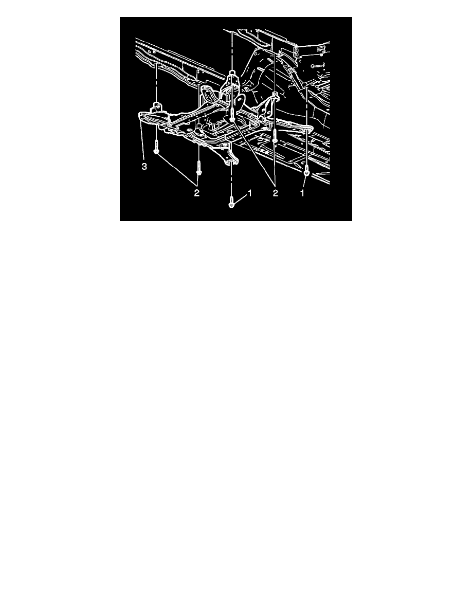
5. Install the frame mountings bolts (2) and tighten to 191 Nm (141 lb ft).
6. Install the frame to body bolts (1) and tighten to 250 Nm (180 lb ft)
7. Raise the vehicle.
8. Install the engine mount lower retaining nuts (2) and tighten to 50 Nm (37 lb ft).
9. Remove the J 39580 from under the vehicle.
10. Install the power steering and brake line retainers to the frame.
11. Remove the mechanics wire supporting the power steering gear.
12. Install the power steering gear mounting bolts. Refer to Steering Gear Replacement (Left Hand Drive With All Wheel Drive) (See: Steering and
Suspension/Steering/Steering Gear)Steering Gear Replacement (Left Hand Drive With Rear Wheel Drive) (See: Steering and
Suspension/Steering/Steering Gear)Steering Gear Replacement (Right Hand Drive) (See: Application and ID).
13. Install the lower control arms. Refer to Lower Control Arm Replacement (AWD) (See: Steering and Suspension/Suspension/Control Arm/Service
and Repair/Front Suspension)Lower Control Arm Replacement (FWD) (See: Steering and Suspension/Suspension/Control Arm/Service and
Repair/Front Suspension).
Note: Ensure correct position from the previously marked spots.
14. Tighten the stabilizer shaft bolts to 110 Nm (81 lb ft).
15. Install the stabilizer shaft link to the lower control arms. Refer to Stabilizer Shaft Link Replacement (AWD) (See: Steering and
Suspension/Suspension/Stabilizer Bar/Stabilizer Link/Service and Repair/Front Suspension)Stabilizer Shaft Link Replacement (RWD) (See:
Steering and Suspension/Suspension/Stabilizer Bar/Stabilizer Link/Service and Repair/Front Suspension).
16. Install the brake pressure modulator valve to the bracket. Refer to Brake Pressure Modulator Valve Replacement (CTS) (See: Brakes and
Traction Control/Antilock Brakes / Traction Control Systems/Hydraulic Control Assembly - Antilock Brakes/Service and Repair/Brake Pressure
Modulator Valve Replacement)Brake Pressure Modulator Valve Replacement (CTS-V) (See: Brakes and Traction Control/Antilock Brakes /
Traction Control Systems/Hydraulic Control Assembly - Antilock Brakes/Service and Repair/Brake Pressure Modulator Valve Replacement).
17. Install the brake pipes to the frame.
18. Remove the mechanics wire supporting the radiator.
19. Install the wheel speed sensor wire harness to the frame.