
CTS Sedan AWD V6-3.0L (2010)
Right Hand Side Instrument Panel Plastic Retainer Cut Procedure
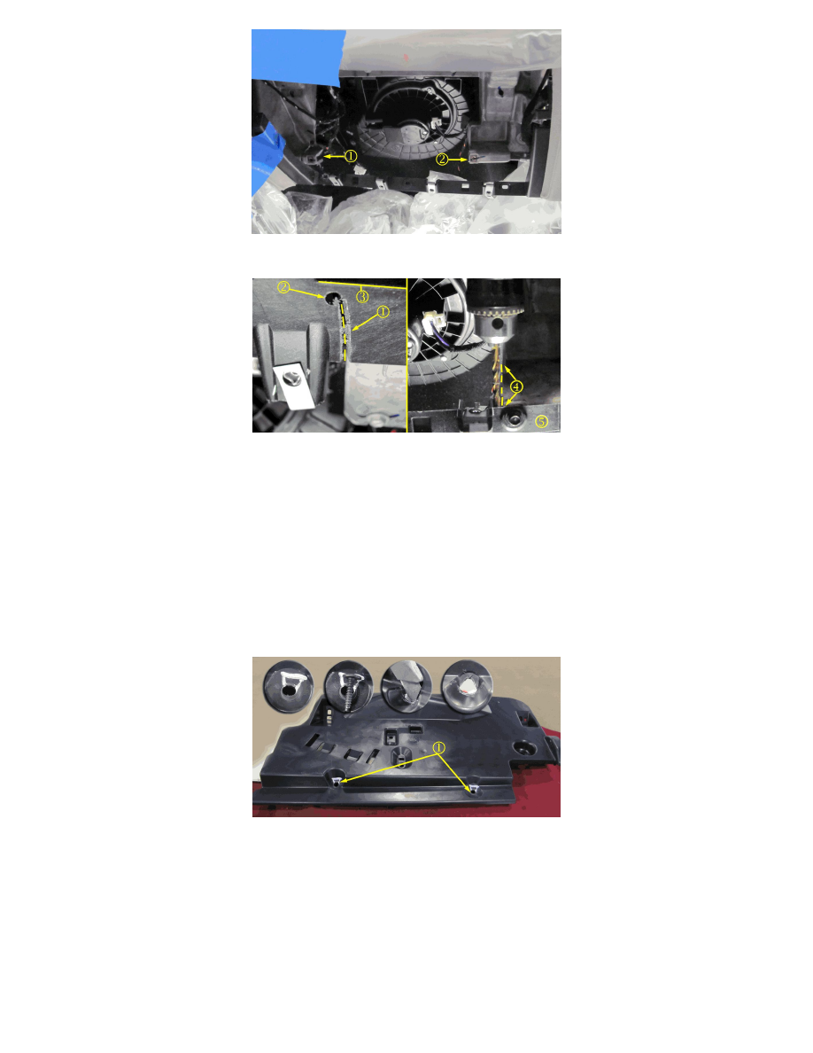
Left portion of illustration shows the underside of the instrument panel plastic retainer. Right portion of the illustration shows the front and topside of the
instrument panel plastic retainer.
Note
The cut line should follow the edge of the outboard passenger side magnesium beam cut made in Step 9.5. Refer to Outboard Passenger Side
Lower Magnesium Beam Cut Completed in the Step 9.5 illustration. Callout 2 shows the pre-drill of the outboard passenger side cut. End the cut
line 1-2 mm (3/64-5/64 in) before the front face (5) surface edge (3) of the instrument panel plastic retainer.
15. Using a pen, mark a cut line (1) on the underside of the instrument panel plastic retainer along the outboard passenger side magnesium beam cut.
16. Drill a hole at the end point of the cut line using a 4.74 mm (3/16 in) drill bit. Drill the hole from the top of the instrument panel plastic retainer as
shown in illustration.
17. Cut the underside of the instrument panel plastic retainer to the hole made in step 16.
Instrument Panel Insulator Screw Hole Cut Procedure
18. Modify the two instrument panel insulator screw holes (1). Refer to illustration.
1. Using a pen, mark an 11 o'clock to 2 o'clock notch into the two screw holes. The notches should be slightly larger than the head of the screws.
2. Using a box cutter (or equivalent tool) cut out the notched area of the screw holes.
19. Remove the plastic cover or drop cloth from the passenger side of vehicle. Clean the remaining debris from the interior.