
CTS Sedan AWD V6-3.0L (2010)
Front Subframe: Service and Repair
Drivetrain and Front Suspension Frame Replacement (All Wheel Drive)
Special Tools
J 39580 Engine Support Stand
Removal Procedure
1. Install the engine support fixture. Refer to Engine Support Fixture (See: Engine, Cooling and Exhaust/Engine/Service and Repair/Removal and
Replacement/Engine Support Fixture).
2. Raise and support the vehicle. Refer to Lifting and Jacking the Vehicle (See: Wheels and Tires/Vehicle Lifting/Service and Repair).
3. Remove the front wheels. Refer to Tire and Wheel Removal and Installation (See: Wheels and Tires/Service and Repair).
4. Remove the front compartment lower noise shield. Refer to Front Compartment Lower Noise Shield Replacement (All Wheel Drive) (See: Body
and Frame/Splash Guard/Service and Repair/Front Compartment Lower Noise Shield Replacement)Front Compartment Lower Noise Shield
Replacement (Rear Wheel Drive) (See: Body and Frame/Splash Guard/Service and Repair/Front Compartment Lower Noise Shield Replacement
).
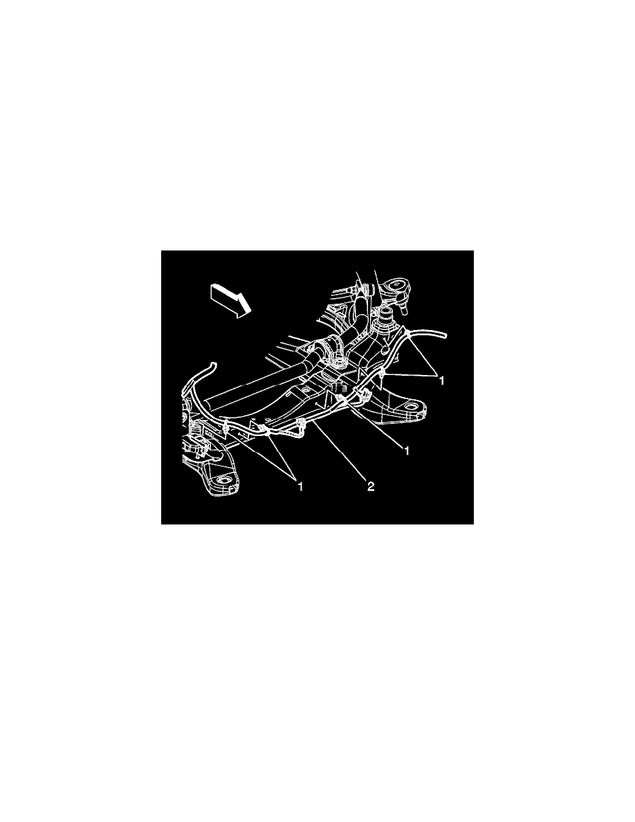
5. Remove the electrical harness retainers (1) securing the engine harness (2) to the frame.
6. Remove the wheel speed sensor wire harness from the frame.
7. Remove the brake pipes from the frame.
8. Remove the brake pressure modulator valve from the bracket assembly. Refer to Brake Pressure Modulator Valve Replacement (CTS) (See:
Brakes and Traction Control/Antilock Brakes / Traction Control Systems/Hydraulic Control Assembly - Antilock Brakes/Service and
Repair/Brake Pressure Modulator Valve Replacement)Brake Pressure Modulator Valve Replacement (CTS-V) (See: Brakes and Traction
Control/Antilock Brakes / Traction Control Systems/Hydraulic Control Assembly - Antilock Brakes/Service and Repair/Brake Pressure Modulator
Valve Replacement).
9. Using mechanics wire, support the radiator and AC condenser assembly to the vehicle body.
Note: Mark the stabilizer shaft to ensure the correct position when reinstalling.
10. Loosen the stabilizer shaft mounting bolts.
11. Remove the antilock brake system wire harness from the sway bar links.
12. Remove the lower stabilizer shaft link from the lower control arm. Refer to Stabilizer Shaft Link Replacement (AWD) (See: Stabilizer
Bar/Stabilizer Link/Service and Repair/Front Suspension)Stabilizer Shaft Link Replacement (RWD) (See: Stabilizer Bar/Stabilizer Link/Service
and Repair/Front Suspension).
13. Remove the power steering gear mounting bolts. Refer to Steering Gear Replacement (Left Hand Drive With All Wheel Drive) (See:
Steering/Steering Gear)Steering Gear Replacement (Left Hand Drive With Rear Wheel Drive) (See: Steering/Steering Gear)Steering Gear
Replacement (Right Hand Drive) (See: Application and ID).
14. Using mechanics wire secure the power steering gear to the engine.
15. Remove the lower control arms. Refer to Lower Control Arm Replacement (AWD) (See: Control Arm/Service and Repair/Front Suspension