
DeVille V8-252 4.1L VIN 8 FI (1983)
Crankshaft Main Bearing: Service and Repair
*** UPDATED BY TSB 84-5C, DATED MARCH 1986
*** UPDATED BY TSB 92-132, DATED SEPTEMBER 1992
V8-250
Rod bearings are supplied by Cadillac in standard sizes only.
Main bearing are supplied by Cadillac in various sizes.
NOTE: Refer to piston and rod assembly for removal procedures.
MODELS AFFECTED: 1982-1988 ELDORADO, SEVILLE, FLEETWOOD, DE VILLE AND BROUGHAM.
1.
HT4100 Engine Knock
Some Cadillacs equipped with an HT4100 engine may experience an engine knock. Engines experiencing this condition should be serviced as
follows:
A.
Visually inspect for proper piston installation, off centered wrist pins, and piston to crankshaft interference and repair as required.
B.
Inspect for crankshaft to block interference. Some engines may require the installation of a machined counterweight crankshaft when
interference is evident. This crankshaft is P/N 1629092 for transverse engines or 1629093 for longitudinal engines.
C.
Using the following plastic gauging procedure, measure the #1 main bearing to crankshaft clearance.
NOTICE:
Main bearing clearance specifications are for an assembled engine (cylinder heads and intake manifold installed and torqued to
specifications). Because bearing clearances differ significantly between a non-assembled and an assembled engine, bearing clearance
measurements should be made on an assembled engine only. Measuring bearing clearances on a non-assembled engine may result in
incorrect readings.
#1 Main Bearing Clearance Checking
Remove and discard the existing #1 bearings and install new current production #1 main bearings (P/N 18014329), which can be identified
by a red edge color, in the #1 main bearing bore. Using the procedures detailed below, measure the clearance with this bearing.
1.
With main bearing cap removed, wipe oil from crankshaft journal and bearing insert.
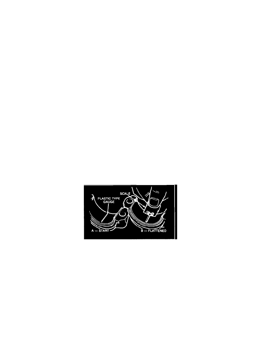
FIGURE 1 - CLEARANCE
2.
Place a piece of plastic gauging material in center of cap (Figure 1). When using plastic gauging material, plastic material and part
being measured must both be at room temperature. If parts are excessively warm, an incorrect reading may result. Fresh plastic
gauging material is recommended for greatest accuracy.
3.
Reinstall main bearing cap. Tighten main bearing cap screws to 115 N-m (85 ft. lbs.).
When bearings are being measured with engine in chassis, crankshaft must be supported in order to take up clearance between
upper bearing shell and crankshaft. This can be done by removing bearing caps adjacent to bearing being checked and placing a
strip of .005 (0.13 mm) inch brass shim stock between lower bearing shell and crankshaft bearing journal.
When reinstalling bearing caps with shims, lightly tighten attaching screws to avoid damaging bearing caps.
NOTICE:
It is extremely important to position tangs on bearings in notches in block and cap or both could be damaged.
4.
Remove main bearing cap and determine clearance by comparing width of flattened plastic gauging material at its widest point, with
graduations on plastic gauging material container. Number within matching graduation on envelope indicates clearance (Figure 1).