
DeVille V8-252 4.1L VIN 8 FI (1983)
Intake Manifold: Service and Repair
V8-250
Some vehicles equipped with V8-250 engine may have oil leakage at the intake manifold to block seal. This may be caused by a split intake
manifold seal. To correct this problem, new silicone end seals were put into production during 1984.
The seals, which can be identified by their gray color are part of gasket set 3634619 and can be used to service older model engines.
1.
Drain coolant from radiator, then disconnect radiator hose from thermostat housing.
2.
Disconnect electrical connectors from coolant sensor, MAT sensor, throttle position sensor, distributor, ISC motor and fuel injectors.
3.
Disconnect heater hoses from manifold.
4.
Disconnect fuel lines from throttle body and remove distributor.
5.
Remove both rocker arm covers.
6.
Remove rocker arm support and rocker arms as an assembly.
7.
Remove bolts securing A/C compressor, then position compressor aside with all hoses and lines attached.
8.
Remove vacuum harness connectors from rear of manifold.
9.
Remove intake manifold bolts and lower thermostat housing to front cover bolts. Engine lift brackets must be bent or positioned aside for
intake manifold removal.
10.
Remove intake manifold by lifting straight up off dowels.
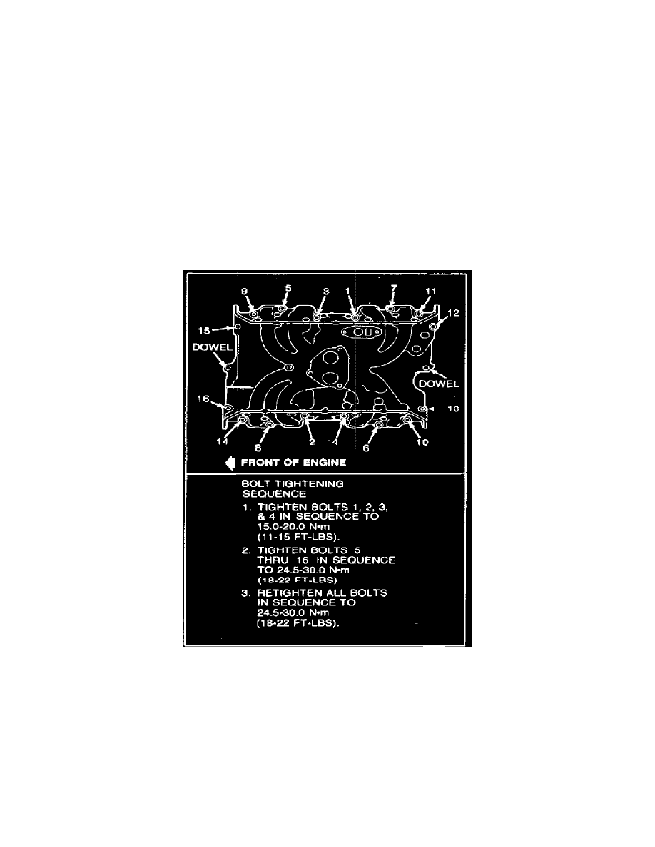
Fig. 3 Intake manifold bolt tightening sequence. V8-250
11.
Reverse procedure to install. Refer to Fig. 3 for intake manifold bolt tightening sequence and torque procedure.
The V8-250 engine uses three different intake manifolds, all using different intake manifold to cylinder head bolts. To determine which
manifold and bolts are used, an identification mark is located next to the manifold air temperature sensor.
The first type manifold has no identification mark. Bolt location, Fig. 3, and size are as follows: locations 1, 2, 3, 4, 12, 13 and 16; 1.57 inch
(40 mm) bolts; locations 5, 6, 7, 8, 9, 10, 11 and 14; 1.18 inch (30 mm) bolts; and location 15; 2.36 inch (60 mm) bolt.
The second type manifold is identified by an X. Bolt location, Fig. 3, and sizes are as follows: locations 1, 2, 3 and 4; 2.16 inch (55 mm) bolts;
locations 5, 6, 7, 8, 9, 10, 11 and 14; 1.18 inch (30 mm) bolts; locations 12, 13 and 16; 1.57 inch (40 mm) bolts; and location 15, 2.36 inch (60 mm) bolt.
The third type manifold is identified by a circled X. This manifold uses the same bolts in the same location as the manifold with the X
identification mark, with the exception of bolt 12. In this manifold a 2.16 inch (55 mm) bolt is used, Fig. 3.