
DeVille V8-300 4.9L (1993)
Follow the steps below to repair Weather Pack(R) connectors.
Step 1:
Separate the connector halves.
Step 2:
Open secondary lock. A secondary lock aids in terminal retention and is usually molded to the connector.
Step 3:
Grasp the lead and push the terminal to the forward most position. Hold the lead at this position.
Step 4:
Insert the Weather Pack(R) terminal removal tool into the front (mating end) of the connector cavity until it rests on the cavity shoulder.
Step 5:
Gently pull on the lead to remove the terminal through the back of the connector.
NOTE: NEVER use force to remove a terminal from a connector.
Step 6:
Inspect the terminal and connector for damage. Repair as necessary (refer to Terminal Repair). See: Typical Electrical Repair
Procedures/Terminal Repairs
Step 7:
Re-form the lock tang and reseat terminal in connector body.
Step 8:
Close secondary locks and join connector halves.
Diode Replacement
Many vehicle electrical systems use a diode to isolate circuits and protect the components from voltage spikes. When installing a new diode, use the
following procedure:
Step 1: Open the Harness
If the diode is taped to the harness, remove all of the tape.
Step 2: Remove inoperative Diode
Paying attention to current flow direction, remove inoperative diode from the harness with a suitable soldering tool. If the diode is located next to a
connector terminal, remove the terminal(s) from the connector to prevent damage from the soldering tool.
Step 3: Strip the Insulation
Carefully strip away a section of insulation next to the old soldered portion of the wire(s). Do not remove any more than is needed to attach the
new diode.
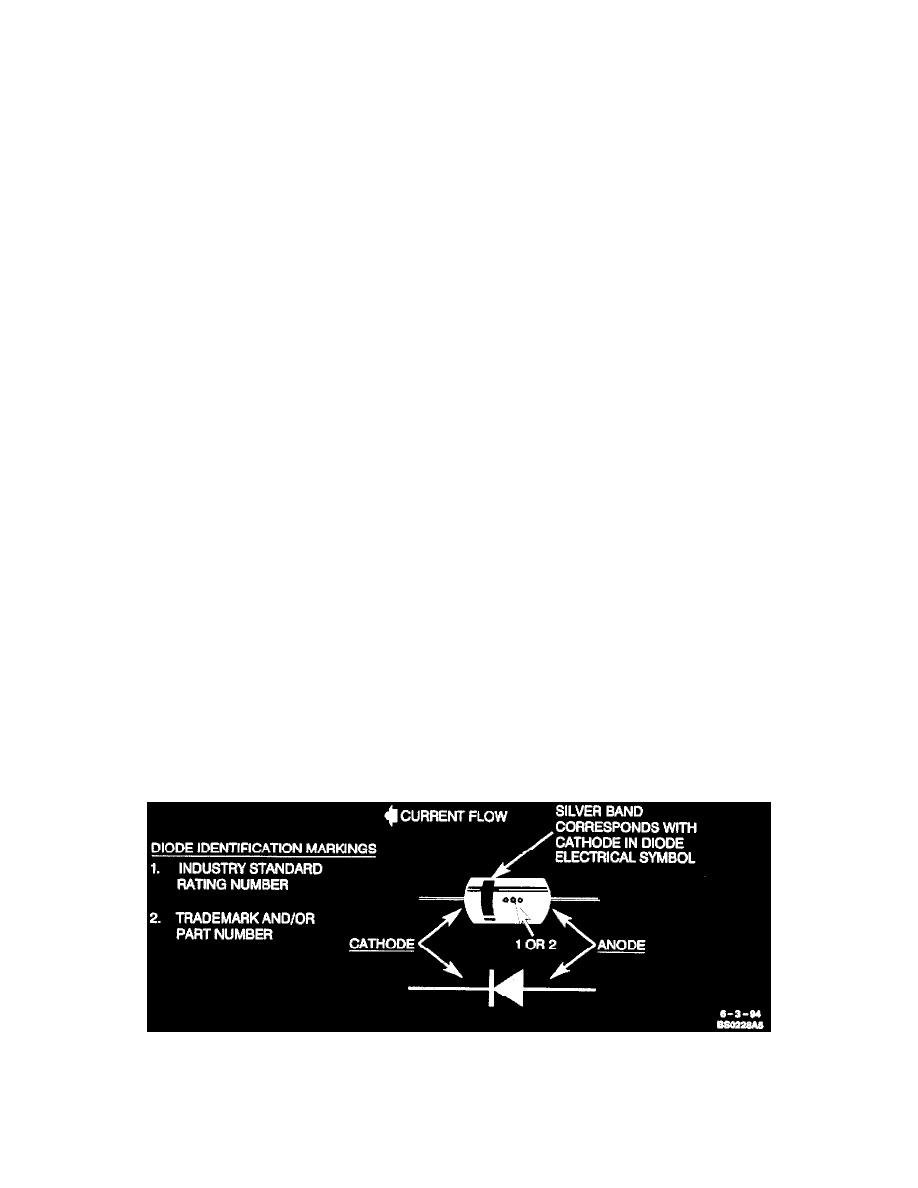
Diode Identification
Step 4: Install New Diode
Check current flow direction of the new diode, being sure to install the diode with correct bias. Refer the image for replacement diode symbols and
current flow explanations. Attach the new diode to the wire(s) using 60/40 rosin core solder. Use a beat sink (aluminum alligator clip) attached
across the diode wire ends to protect the diode from excess heat. Follow the manufacturer's instructions for the soldering equipment you are using.