
DeVille V8-4.6L VIN 9 (1995)
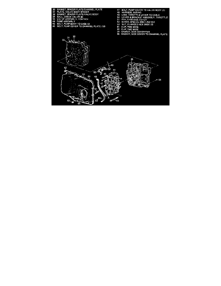
Fig.8 Valve Body Assembly.
1. Disconnect battery ground cable and remove air cleaner.
2. Install engine support fixture tool No. J-28467 or equivalent.
3. Remove upper side cover retaining bolts and the fuel pipe bracket.
4. Raise and support vehicle, and remove left front wheel.
5. Disconnect stabilizer shaft from left control arm, noting position of bushings and spacers.
6. Support control arm using suitable jack, then disconnect ball joint from left steering knuckle using suitable puller.
7. Remove left engine splash shield.
8. Remove vacuum pump mounting bolts and secure pump aside, leaving hoses connected.
9. Install drive boot seal protector tool No. J-34754 or equivalent.
10. Disconnect left drive axle from transaxle and secure aside, taking care not to extend drive axle joints.
11. Support transaxle using suitable jack and remove left front transaxle mount.
12. Remove right front engine mount as follows:
a. Vehicle should be supported at each front frame horn to prevent vehicle from tipping on hoist.
b. Disconnect brace between engine bracket and engine.
c. Remove two nuts securing mount to frame.
d. Remove two nuts securing transaxle bracket to mount.
e. Remove two nuts securing transaxle mount to frame bracket.
f.
Raise engine using support fixture, then remove stud and two bolts securing mount bracket to block.
g. Remove mount and bracket by pulling forward.
13. Loosen left and right rear transaxle mounts.
14. Remove left cradle mounts, separate left cradle and remove from vehicle, Fig. 9 and 10 .
15. Loosen but do not remove right cradle mounts 2 and 3.
16. Remove jacks. Ensure vehicle remains stable, then lower vehicle.
17. Note position of engine support fixture support rods and lower engine/transaxle assembly as follows.
NOTE: In order to obtain maximum clearance for side cover removal it is necessary to tilt front of engine downwards.
a. Move left (driver's side) rear support rod until it extends approximately six inches above T nut.
b. Lower left front support rod until top is flush with top of T nut.
18. Raise and support vehicle.
19. Disconnect transaxle cooler lines from bracket and secure aside.
20. Remove remaining side cover retaining bolts and nuts securing axle opening cover.
21. Remove side cover pan and gaskets.
22. Remove wiring harness and VCC solenoid, disconnecting harness from pressure switches and case connector.
23. Remove TV lever, bracket and link assembly.
24. Remove oil pump retaining bolts and the pump assembly.
CAUTION: Do not remove three bolts (A), Fig. 8, securing pump cover to valve body.