
DeVille V8-4.6L VIN Y (1998)
Blower Motor: Service and Repair
Revised Front Blower Motor Replacement
This article has been updated with bulletin No.: 03-01-37-002
REVISED HVAC BLOWER MOTOR INSTALLATION PROCEDURES
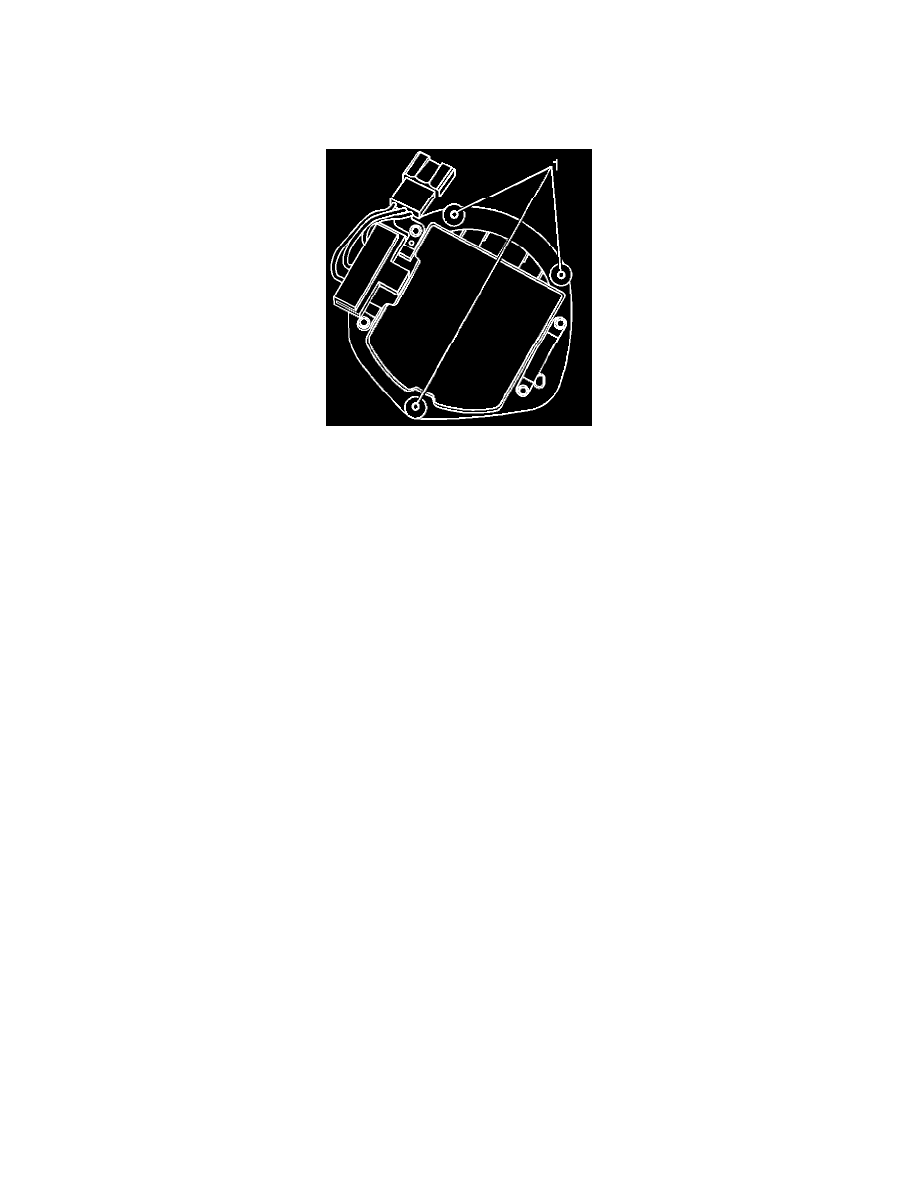
The current available HVAC Module blower motor for the above listed vehicles can be identified by the three mounting holes (1). The original
equipment blower motor had five mounting holes.
In order to avoid confusion and ensure a high level of customer satisfaction, when replacing an HVAC Module blower motor, refer to this bulletin for
the appropriate procedure.
CAUTION: Before servicing any electrical component, the ignition key must be in the OFF or LOCK position and all electrical loads must
be OFF, unless instructed otherwise in these procedures. If a tool or equipment could easily come in contact with a live exposed electrical
terminal, also disconnect the negative battery cable. Failure to follow these precautions may cause personal injury and/or damage to the
vehicle or its components.
REMOVAL PROCEDURE
1. Disconnect the negative battery cable.
2. Remove the cross-car brace.
3. Disconnect and position the ignition control module assembly out of the way.
4. Position the cross-car harness out of the way.
5. Remove the solenoid purge valve.
6. Remove the blower motor.
^
Disconnect connector from the blower motor.
^
Remove the blower motor screws (either 3 or 5 screws).
^
Remove the blower motor from the HVAC Module.
INSTALLATION PROCEDURE
1. If present, remove the 2 ribs located on the barrier. Refer to Step 3 and the illustrations in the Instruction Sheet, P/N, 52494110, found in the
blower motor kit.
IMPORTANT: Ensure the blower motor gasket makes a complete seal around the blower motor.
2. Install the new blower motor with heat shield. Refer to Steps 4 and 5 in the Instruction Sheet, P/N 52494110, found in the blower motor kit.
3. Install the blower motor retaining screws.
TIGHTEN
^
Screws to 4 Nm (35 lb. in.).
4. Tighten the lower heat shield retaining screws to 4 Nm (35 lb in).
5. Connect the connector to the blower motor.
6. Install the solenoid purge valve.
7. Reposition and connect the ignition control module assembly.
8. Install the cross-car brace.
9. Connect the negative battery cable.