
DeVille V8-4.6L VIN Y (1998)
INSTALLATION
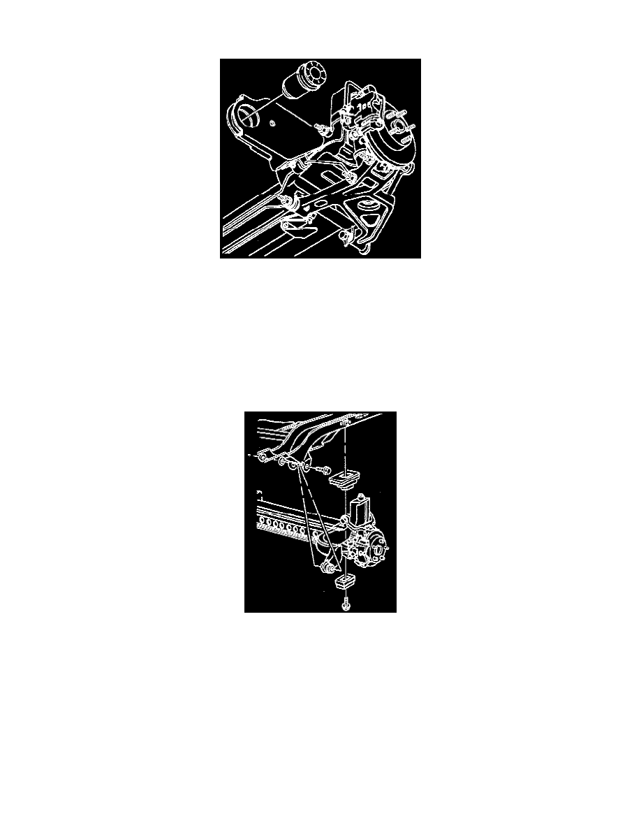
1. Position the new bushing for installation on the forward arm.
^
The bushing must be installed with the notches on the bushing flange at the 12 o'clock and 6 o'clock positions.
^
The bushing must be installed from the outboard side of the forward arm and drawn inward toward the vehicle centerline.
2. Insert the J 35739 Rear Control Arm Bushing Service Set between the forward arm flanges.
3. Coat the threads of the J 21474-19 with High Pressure Lubricant in order to prevent thread damage.
4. Install the J 35739 Rear Control Arm Bushing Service Set, the J 21474-5, the J 21474-1fl and the J 21474-19.
5. Draw the bushing into the forward arm by tightening the nut. Tighten the nut until the bushing flange seats firmly against the arm.
6. Check the upper suspension support insulators for proper positioning.
IMPORTANT: While raising the suspension support, carefully watch the position of the brake calipers, hoses and pipes. Reposition the calipers,
pipes and hoses as required in order to prevent interference or damage to the brake components.
7. Slowly raise the suspension support. Align the suspension support with the body as it is raised.
IMPORTANT:
^
Both forward arm bolts must be installed in the proper direction, with the nuts installed on the right side of the arm.
^
The cup-shaped washer is used on the left forward arm bolt installation only.
NOTICE: Use the correct fastener in the correct location. Replacement fasteners must be the correct part number for that application. Fasteners
requiring the use of thread locking compound or sealant are identified in the service procedure. Do not use paints, lubricants, or corrosion
inhibitors on fasteners or fastener joint surfaces unless specified. These coatings affect fastener torque and joint clamping force and may damage
the fastener. Use the correct tightening sequence and specifications when installing fasteners in order to avoid damage to parts and systems.
8. Install the suspension support forward arm bolts, nuts and washers, the upper mounting bolts and the insulators.
^
Tighten the right side suspension support forward arm nut to 63 Nm (46 ft. lbs.).
^
Tighten the left side suspension support forward arm bolt to 102 Nm (75 ft. lbs.).
^
Tighten the upper mounting bolts to 102 Nm (75 ft. lbs.).