
DeVille DHS V8-4.6L VIN Y (2000)
Diagnostic Chart
CIRCUIT DESCRIPTION
The data link connector (DLC) provides operating power for the scan tool at terminal 16 (battery positive voltage) and at terminal 4 (ground). The
DLC provides the class 2 serial data signal at terminal 2 and signal ground at terminal 5. The scan tool will power up with the ignition off. Some
modules, however, will not communicate unless the ignition is on and the dash integration module (DIM) sends the appropriate power mode message.
TEST DESCRIPTION
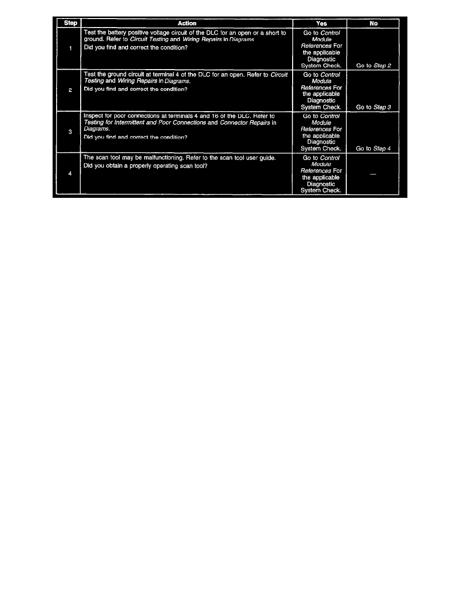
The number(s) below refer to the step number(s) on the diagnostic table.
1. The ALDL fuse supplies power to terminal 16 of the DLC.
4. The battery positive voltage and ground circuits of the DLC are functioning properly. The malfunction must be due to the scan tool.