
DeVille DHS V8-4.6L VIN Y (2000)
Intake Air Temperature (IAT) Sensor: Description and Operation
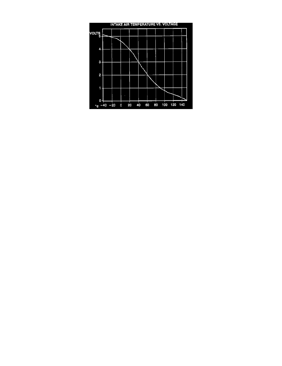
Voltage Versus Temperature Chart
The Intake Air Temperature (IAT) sensor is a thermistor integrated with the Mass Air Flow (MAF) sensor. The IAT sensor resistance varies from
100,000 ohms at 40°C (40°F) to 70 ohms at 130°C (266°F). The PCM uses the AT signal to calculate the intake air temperature. The PCM applies 5
volts to the IAT signal circuit through a pull-up resistor. When the intake temperature is cold, the IAT sensor resistance is high. This causes the PCM to
detect a high IAT signal voltage. As the underhood temperatures increase, the IAT sensor resistance lowers. The PCM should detect a low IAT signal
voltage.
The scan tool displays the intake air temperature in degrees. The IAT sensor display should read close to ambient air temperature when the engine is
cold. As the underhood temperature increases, the IAT sensor display should also increase. If the engine has not been run for several hours (overnight),
the IAT sensor and ECT sensor scan tool displays should read close to each other. A hard fault in the IAT sensor circuit should set DTC P0112 or
P0113. An intermittent fault should set DTC P1111 or DTC P1112. To check IAT sensor resistance relative to temperature, refer to the Temperature Vs
Resistance table. See: Specifications