
Escalade ESV RWD V8-6.2L (2010)
Housing Assembly HVAC: Service and Repair
Air Conditioning and Heater Module Assembly Removal and Installation
Air Conditioning and Heater Module Assembly Removal and Installation (Non-HP2)
Special Tools
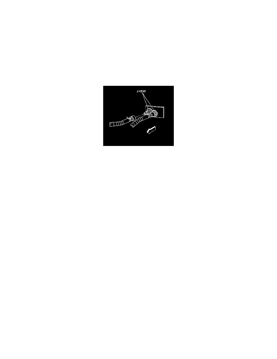
J 43181 Heater Line QC Release Tool
Removal Procedure
1. Drain the engine coolant. Refer to Cooling System Draining and Filling (Static Fill) (See: Engine, Cooling and Exhaust/Cooling System/Service
and Repair/Cooling System Draining and Filling (Static Fill)).
2. Using the J 43181 disconnect the inlet heater hose from the heater core.
1. Install the J 43181 to the heater core pipe.
2. Close the tool around the heater core pipe.
3. Firmly pull the tool into the quick connect end of the heater hose.
4. Firmly grasp the heater hose. Pull the heater hose forward in order to disengage the inlet hose from the heater core.
3. Using the J 43181 disconnect the surge tank outlet hose from the heater core.
1. Install the J 43181 to the heater core pipe.
2. Close the tool around the heater core pipe.
3. Firmly pull the tool into the quick connect end of the heater hose.
4. Firmly grasp the heater hose. Pull the heater hose forward in order to disengage the surge tank outlet hose from the heater core.
4. Remove the upper intake manifold sight shield. Refer to Upper Intake Manifold Sight Shield Replacement (See: Engine, Cooling and
Exhaust/Engine/Intake Manifold/Service and Repair/Upper Intake Manifold Sight Shield Replacement).
5. Remove the battery. Refer to Battery Replacement (See: Starting and Charging/Battery/Service and Repair/Removal and Replacement).
6. Remove the accumulator. Refer to Air Conditioning Accumulator Replacement (HP2) (See: Accumulator HVAC/Service and Repair)Air
Conditioning Accumulator Replacement (Non-HP2) (See: Accumulator HVAC/Service and Repair).
7. Remove the instrument panel to the service position. Refer to Instrument Panel Service Positioning (With SLT) (See: Body and Frame/Interior
Moulding / Trim/Dashboard / Instrument Panel/Service and Repair/Instrument Panel Service Positioning (With SLT))Instrument Panel Service
Positioning (Cadillac) (See: Body and Frame/Interior Moulding / Trim/Dashboard / Instrument Panel/Service and Repair/Instrument Panel and
Console Trim/Instrument Panel Service Positioning (Cadillac)).
8. Remove the HVAC module drain hose.
9. Disconnect the electrical harnesses and the ground connections from the HVAC module.