
Escalade ESV RWD V8-6.2L (2010)
Heated Glass Element: Testing and Inspection
Rear Window Defogger Malfunction
Diagnostic Instructions
*
Perform the Diagnostic System Check - Vehicle (See: Testing and Inspection/Initial Inspection and Diagnostic Overview/Diagnostic System
Check - Vehicle) prior to using this diagnostic procedure.
*
Review Strategy Based Diagnosis (See: Testing and Inspection/Initial Inspection and Diagnostic Overview/Strategy Based Diagnosis) for an
overview of the diagnostic approach.
*
Diagnostic Procedure Instructions (See: Testing and Inspection/Initial Inspection and Diagnostic Overview/Diagnostic Procedure Instructions)
provides an overview of each diagnostic category.
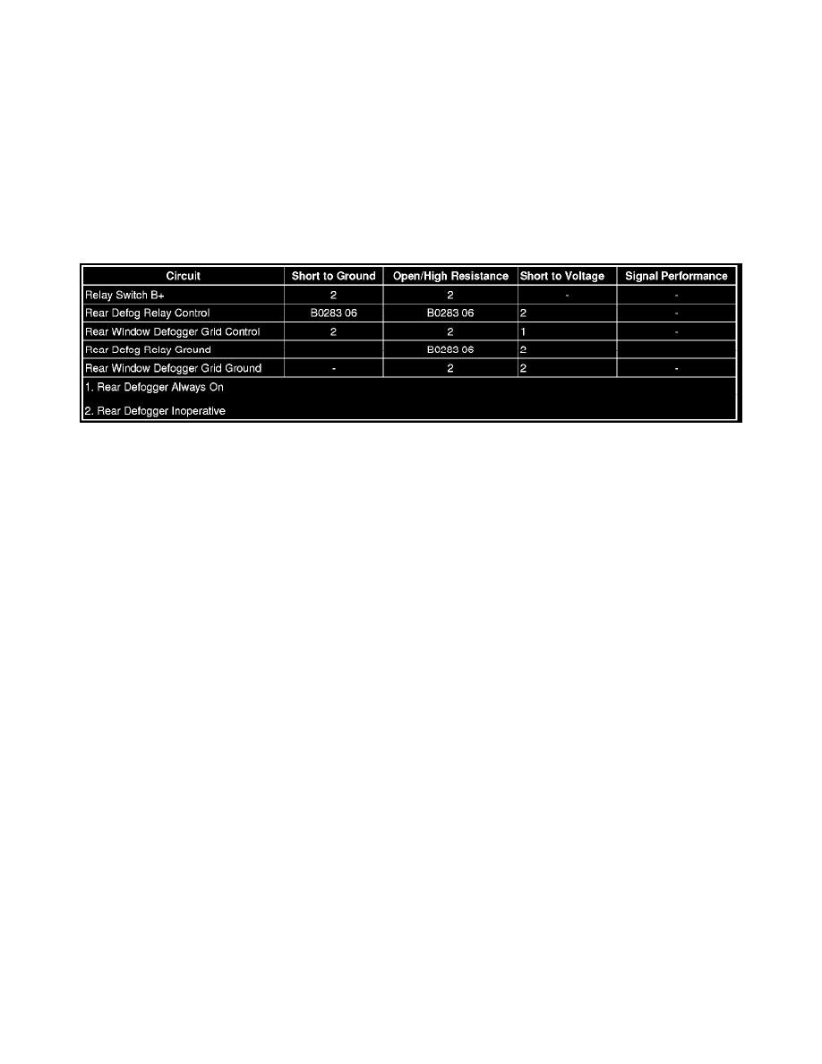
Diagnostic Fault Information
Circuit/System Description
When the rear defogger button is pressed, voltage is supplied to the relay coil by the HVAC control module which also illuminates the rear window
defogger indicator. B+ voltage is supplied at all times to the relay switched input and the relay coil is always grounded. This allows battery positive
voltage from the relay switched input through the switch contacts and out the relay switched output to the rear window defogger.
Reference Information
Schematic Reference
Defogger Schematics (See: Diagrams/Electrical Diagrams)
Connector End View Reference
Component Connector End Views (See: Diagrams/Connector Views)
Description and Operation
Rear Window Defogger Description and Operation (See: Windows/Description and Operation/Rear Window Defogger Description and Operation)
Electrical Information Reference
*
Circuit Testing (See: Testing and Inspection/Component Tests and General Diagnostics/General Electrical Diagnostic Procedures/Circuit
Testing/Circuit Testing)
*
Connector Repairs (See: Testing and Inspection/Component Tests and General Diagnostics/General Electrical Diagnostic Procedures/Connector
Repairs/Connector Repairs)
*
Testing for Intermittent Conditions and Poor Connections (See: Testing and Inspection/Component Tests and General Diagnostics/General
Electrical Diagnostic Procedures/Circuit Testing/Testing for Intermittent Conditions and Poor Connections)
*
Wiring Repairs (See: Testing and Inspection/Component Tests and General Diagnostics/General Electrical Diagnostic Procedures/Wiring
Repairs/Wiring Repairs)
Scan Tool Reference
Control Module References (See: Testing and Inspection/Programming and Relearning) for scan tool information
Circuit/System Verification
1. Ignition ON, observe the scan tool Rear Defrost State parameter while pressing the rear window defogger switch. The parameter should change
between On and Off.
‹› If the parameter does not change between the commanded states, replace the HVAC control module.
2. Observe the operation of the rear window defogger indicator while pressing the rear window defogger switch. The indicator should turn ON or