
Escalade V8-5.7L VIN R (2000)
hissing is normal.
The air conditioning systems available for the vehicle are the following:
^
C60 Front Manual Controls, HVAC System
^
C69 Rear, HVAC System
UNIT REPAIR INFORMATION
For the bench repair procedures of the Harrison HT-6 air conditioning compressor, refer to HD6/HT6 Air Conditioning Compressor Service Or Unit
Repair R-134a.
For a description of the RPO Code(s) shown in this article/image, refer to the RPO Code List found at Vehicle/Application ID.
See: Application and ID
General
The following air valves are used in the distribution system:
^
The temperature valve
^
The vent valve
^
The defroster valve
Within the heater module is a series of air valves. These air valves are hinged parts that act like doors. The air valves direct the airflow through the
various sections of the heater module in order to provide the proper airflow for the selected operating mode. A control cable from the heater control
assembly actuates each air valve.
Temperature Valve and Heater Core
Controlling the relative amounts of warm air and cool air coming from the heater module regulates the temperature of the air coming from the air
distribution duct. The temperature valve governs the part of the total airflow through the heater module that passes through the heater core. A control
cable, working through a lever on the temperature valve shaft, operates the temperature valve. The valve defaults to full cold with no cable attached.
When the temperature rotary knob in the control assembly is in the full COLD position, the position of the temperature valve stops all of the airflow
through the heater core, so that only unheated air passes to the air distribution duct.
As the temperature rotary knob moves away from the full COLD position, the temperature control cable opens the temperature valve in order to allow
the passage of an increasing amount of air through the heater core. At the same time, the temperature valve reduces the amount of unheated air that enters
the mixture. The result is a very responsive control of the air temperature discharged through the heater ducts and the defroster.
When the temperature rotary knob reaches the full HOT position, the temperature control cable holds the temperature valve in a position that diverts all
of the airflow through the heater core for the maximum heater.
The hot coolant from the engine is directed through the heater core. When the engine is running the hot coolant returns to the cooling system.
Mode Valves
The heater system provides a choice of three basic operating modes:
^
VENT
^
HEATER
^
DEFROST
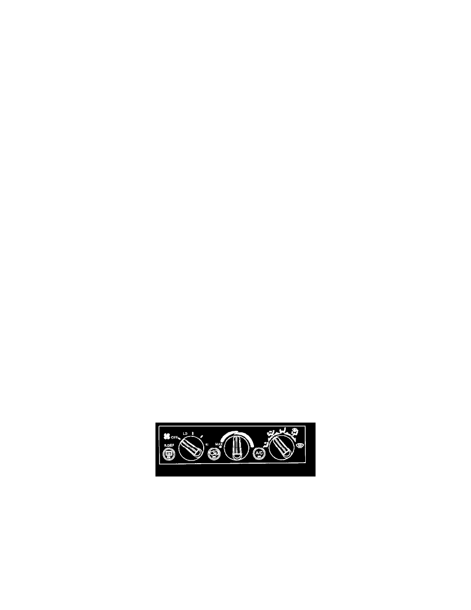
Control Assembly, HVAC
The air conditioning system on C/K models is electronically controlled. Three backlit, rotary knobs provide full control of the system. The rotary knobs
control the following items:
^
The blower speed
^
The air temperature
^
The mode of operation
Two push-to-latch buttons select recirculation mode for maximum cooling and control over the air conditioning compressor.
The blower speed rotary control has 4 fan speeds and an OFF position. When the blower fan is turned off, all the HVAC operations turn off also.
The temperature rotary control has 180 degrees of travel. A detent at the full cold-end of travel engages recirculation. Operating the system with the
temperature control placed in the detent results in maximum cooling. Air inside the passenger compartment recirculates through the blower case. Use of