
Escalade V8-5.7L VIN R (2000)
outside air is minimal. Manually select recirculation by pushing the RECIRC button.
The mode rotary control has 3 major detents that indicate mode positions:
^
The vent
^
The floor
^
The defrost
Placing the control anywhere in between the major detents results in air output blending between the two modes. The recirculation mode is not available
anytime DEFROST is selected, or while air is being blended out of the defrost outlets.
Automatic recirculation occurs when the compressor head pressures exceed 2275 kPa (350 psi) and disables after the head pressures reach 1724 kPa
(250 psi). When activated, automatic recirculation cannot be manually disabled by the MAX button.
Front Ventilation Controls
Vehicles with heating and air conditioning and vehicles with heat only provide front air delivery and temperature controls. The heater only option's
heater control module operates similarly to the HVAC control module except that the A/C pushbutton and temperature dial MAX detent features are not
provided for the control of the recirculation door. An auxiliary cooling fan is provided for vehicles with air conditioning and 7.4L gasoline engines.
Refer to Cooling System Fan Description - Electric in Cooling System. The following are powered by CKT 141 (BRN) when the ignition switch is in the
RUN position.
^
The front mode door motor
^
The front temperature door motor
^
The recirculation door motor
^
The HVAC Control Module
Grounding for the door motors is passes through CKT 150 (BLK) to ground G202. CKT 141 (BRN) powers the HVAC control module when the
ignition switch is in the RUN position. Grounding passes through CKT 150 (BLK) to ground G200 for the IP. The HVAC control module ventilation
controls for the front mode door and the recirculation door are disabled when the module front blower switch is in the OFF position. The ventilation
controls are enabled when the front blower switch is in the HI, M2, M1, or LO positions. The front temperature door is not dependent on the front
blower operations. The front temperature door can be controlled only when the recirculation button on or the A/C is in the max position.
The mode doors and the temperature doors are positioned in proportion to the variable voltage signal received from the HVAC control module. The
temperature dial at the HVAC control module adjusts a rheostat which provides a voltage signal proportional to the dial position. CKT 733 (LT BLU)
carries the voltage to the front temperature door motor. The front temperature door motor responds to the voltage signal. The mode dial at the HVAC
control module adjusts a rheostat. The mode dial provides a voltage signal proportional to the dial position. CKT 454 (WHT) carries voltage to the front
mode door motor. The front mode door motor responds to the voltage signal.
The recirculation door is a 2-position door. The recirculation door is in the recirculation position only when input CKT 1614 (DK GRN) is grounded
through the HVAC control module. The recirculation door is grounded when the auxiliary cooling fan A/C pressure switch operates the auxiliary cooling
fan for air conditioned vehicles with 7.4L gasoline engines. Refer to Cooling System Fan Description - Electric in Cooling System.
The system will be completely shut off with the ignition switch placed in the OFF position. With the ignition switch in the OFF position, CKT 71 (DK
GRN) provides B+ voltage to pin 3, C2 of the HVAC Control module which activates an internal relay removing B+ voltage from the system.
The recirculation door is normally in the outside air position but moves to the inside air position when the input wire is grounded. The LED on the
HVAC control module is illuminated when the recirculation door is grounded through the HVAC control module.
General
An auxiliary heater provides additional heating for the rear of the Suburban model.
This unit operates independently of the standard heater. The auxiliary heater controls in the instrument panel (auxiliary heater models) or in the roof
panel (auxiliary heater and A/C models) regulate the auxiliary heater. The auxiliary heater system consists of a separate heater core and a separate blower
fan unit mounted in the rear of the vehicle.
Blower Motor Control Switch
The location of the auxiliary heater blower switch is in the instrument panel to the right of the steering column (auxiliary heater models) or in the roof
panel (auxiliary heater and A/C models).
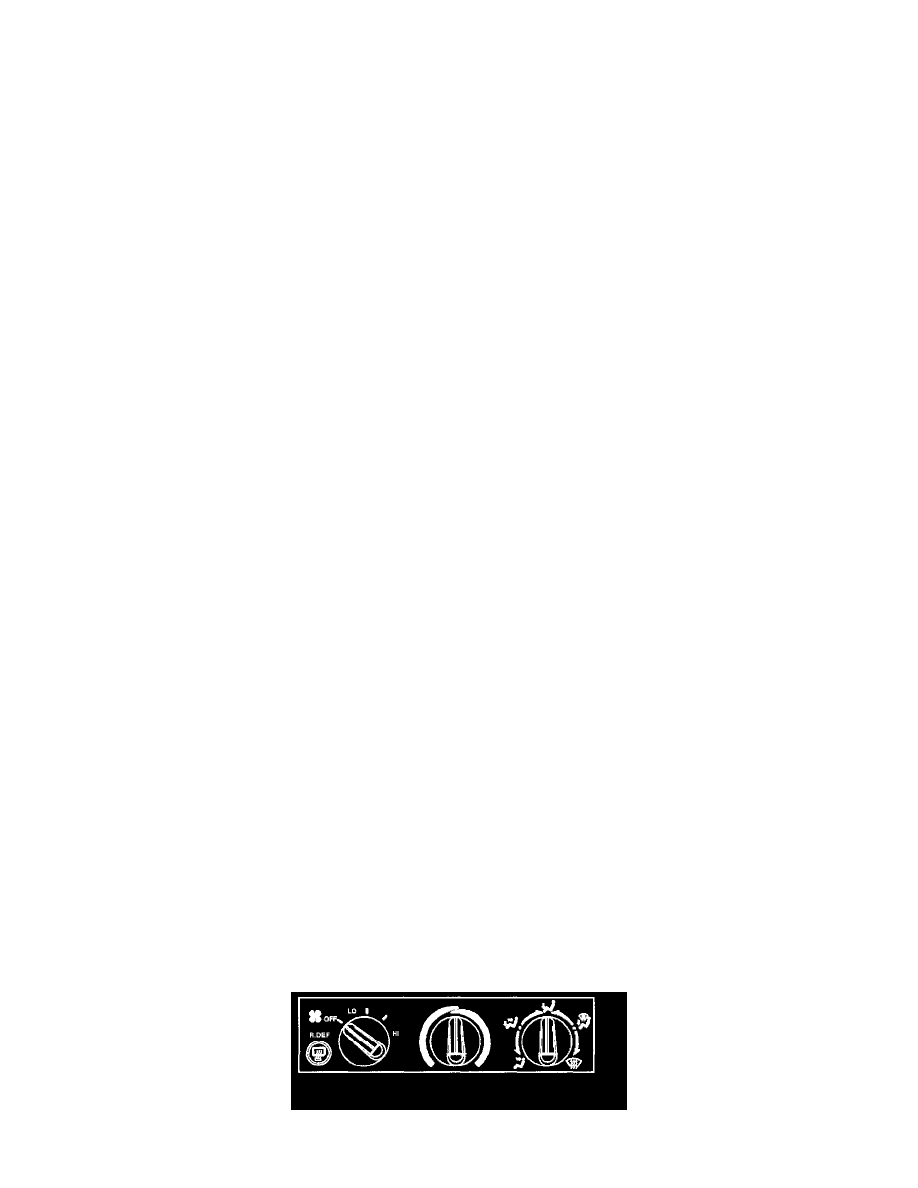
General
The control assembly in the instrument panel contains three rotary control knobs: the blower speed knob, the mode selection knob, and the temperature