
Escalade V8-5.7L VIN R (2000)
Repair the leak.
Restart the evacuation procedure.
8.2. If the display indicates a vacuum of 91- 101 kPa (27-20 in of Hg), close the low-side valve and the high-side valve.
8.3. For a few minutes, observe the vacuum level as a leak check of the A/C system. If the vacuum does not remain, find and repair the leak prior
to continuation of the evacuation.
8.4. If the vacuum maintains a level of 91-101 kPa (27-30 in of Hg), open the high-side valve and the low-side valve.
8.5. Press the HOLD/CONT key in order to restart the vacuum pump.
IMPORTANT:
-
Frequently change the vacuum pump oil.
-
When the pump has run for a total time of 10 hours, the OIL message flashes on the control panel display as a reminder to change the oil.
-
If the OIL warning flashes during the operation, press the CONT key. Change the oil prior to the next operation.
9. When the vacuum sequence completes the programmed time period, the display shows CPL in order to indicate that the evacuation is complete.
Recovering The Refrigerant
1. Connect a battery charger in order to prevent battery drain.
IMPORTANT: Use only the 23 kg (50 lb) unit refrigerant tank (J 39500-50) designed for the ACR4. The calibration of the unit overfill limitation
mechanism is specific for use with this tank. The tank valving is specific for use with the unit.
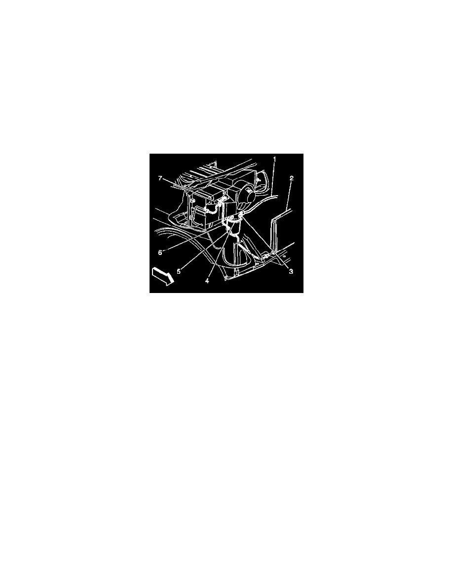
2. Attach the red high-side hose with the quick disconnect coupler to the high-side refrigerant service valve fitting of the vehicle A/C system.
This valve is in the receiver dehydrator tube, between the receiver and dehydrator and the condenser (2).
3. Open the high-side coupler valve.
4. Attach the blue low-side hose with the quick disconnect coupler to the low-side refrigerant charge valve fitting of the vehicle A/C system.
This valve is located between in the compressor and condenser hose, between the compressor and the expansion (orifice) tube.
5. Open the low-side coupler valve.
IMPORTANT: If the A/C system has no refrigerant, do not continue with the recovery operation. A recovery operation without refrigerant draws air
into the recovery tank.
6. Observe the high-side gauge and the low-side gauge on the unit control panel in order to be sure the A/C system has pressure.
No pressure indicates that the system has no refrigerant in need of recovery.
7. Open both the high-side and the low-side valves on the control panel.
8. Open both the red LIQUID and the blue GAS valves on the tank.
9. Slowly open the oil drain valve in order to determine whether the oil separator contains oil.
10. Drain any oil present in the separator into the catch bottle at the bottom of the unit.
11. Close the oil drain valve.
12. Dispose of the oil in the catch bottle in an appropriate manner.
Return the bottle in place on the unit.
13. Plug the unit into the proper voltage outlet.
14. Activate the MAIN POWER switch.
15. Start the engine.
16. With the A/C system in the ON position in order to stabilize the system, idle the engine for a period of one minute.
17. Turn the ignition switch to the OFF position.
18. Connect a battery charger in order to prevent battery drain.
19. Turn the ignition switch to the RUN position.