
Escalade AWD V8-6.2L (2009)
Drink Holders: Testing and Inspection
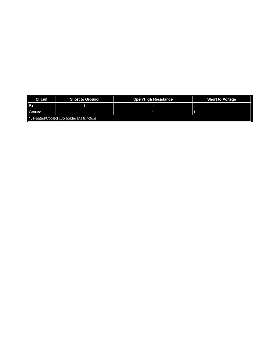
Heated/Cooled Cup Holder Malfunction
Diagnostic Instructions
*
Perform the Diagnostic System Check - Vehicle (with HP2) (See: Testing and Inspection/Initial Inspection and Diagnostic Overview/Diagnostic
System Check - Vehicle)Diagnostic System Check - Vehicle (without HP2) (See: Testing and Inspection/Initial Inspection and Diagnostic
Overview/Diagnostic System Check - Vehicle) prior to using this diagnostic procedure.
*
Review Strategy Based Diagnosis (See: Testing and Inspection/Initial Inspection and Diagnostic Overview/Strategy Based Diagnosis) for an
overview of the diagnostic approach.
*
Diagnostic Procedure Instructions (See: Testing and Inspection/Initial Inspection and Diagnostic Overview/Diagnostic Procedure Instructions)
provides an overview of each diagnostic category.
Diagnostic Fault Information
Circuit/System Description
The Heated/Cooled cup holder system uses a positive temperature coefficient (PTC) ceramic element. The PTC is attached to the side of an aluminum
cylinder that forms the cup holder to provide the temperature change. B+ will either heat or cool the PTC element in the cup holder. Voltage applied in
one direction heats the element and cools it when the polarity is reversed. A momentary switch on the console surface operates the unit. It offers off, heat
and cool settings. The cup holders have a temperature range that heats to 140°F or cools to 35°F. A light in the switch glows red to indicate heating and
blue to indicate cooling.
Reference Information
Schematic Reference
Heated/Cooled Cupholder Schematics See: Diagrams
Connector End View Reference
Component Connector End Views (See: Diagrams/Connector Views)
Description and Operation
Heated/Cooled Cup Holder Description and Operation (See: Description and Operation)
Electrical Information Reference
*
Circuit Testing (See: Testing and Inspection/Component Tests and General Diagnostics)
*
Connector Repairs (See: Testing and Inspection/Component Tests and General Diagnostics)
*
Testing for Intermittent Conditions and Poor Connections (See: Testing and Inspection/Component Tests and General Diagnostics)
*
Wiring Repairs (See: Testing and Inspection/Component Tests and General Diagnostics)
Scan Tool Reference
Control Module References (See: Testing and Inspection/Programming and Relearning) for scan tool information
Circuit/System Verification
Ignition ON, turn the Heated/Cooled cup holder ON. Feel the inside of the Heated/Cooled cup holder it should feel warm or cool to the touch within a
few minutes depending on the switch position.
Circuit/System Testing
1. Ignition OFF, disconnect the harness connector at the Heated/Cooled cup holder.
2. Test for less than 10 ohms between the ground circuit terminal A and ground.
‹› If greater than the specified range, test the ground circuit for an open/high resistance.
3. 2. Ignition ON, verify that a test lamp illuminates between the B+ circuit terminal D and ground.