
Escalade AWD V8-6.2L (2009)
circuits. These terminals are available in the J-38125 . If the individual terminals are damaged on any GMLAN connection, use the appropriate
connector repair procedure in order to repair the terminal. Refer to Connector Repairs (See: Testing and Inspection/Component Tests and General
Diagnostics) for the appropriate connector repair procedure.
GMLAN Wire Repair
Note: Refer to Wiring Repairs (See: Testing and Inspection/Component Tests and General Diagnostics) in order to determine the correct wire size for
the circuit you are repairing. You must obtain this information in order to ensure circuit integrity.
If a wire is damaged, repair the wire by splicing in a new section of wire of the same gage size (0.5 mm, 0.8 mm, 1.0 mm, etc.). Use the DuraSeal splice
sleeves and splice crimping tool from the J-38125 . Use the following wiring repair procedures in order to ensure the integrity of the sealed splice.
Note: You must perform the following procedures in the listed order. Repeat the procedure if any wire strands are damaged. You must obtain a
clean strip with all of the wire strands intact.
1. Open the harness by removing any tape:
*
Use a sewing seam ripper, available from sewing supply stores, in order to cut open the harness in order to avoid wire insulation damage.
*
Use the DuraSeal splice sleeves on all types of insulation except tefzel and coaxial.
*
Do not use the crimp and DuraSeal splice sleeve to form a splice with more than 2 wires coming together.
2. Cut as little wire off the harness as possible. You may need the extra length of wire in order to change the location of a splice.
Adjust splice locations so that each splice is at least 40 mm (1.5 in) away from the other splices, harness branches, or connectors.
3. Strip the insulation:
*
When adding a length of wire to the existing harness, use the same size wire as the original wire.
*
Perform one of the following items in order to find the correct wire size:
-
Find the wire on the schematic and convert the metric size to the equivalent American wire gage (AWG) size.
-
Use an AWG wire gage.
-
If you are unsure of the wire size, begin with the largest opening in the wire stripper and work down until achieving a clean strip of the
insulation.
*
Strip approximately 7.5 mm (0.313 in) of insulation from each wire to be spliced.
*
Do not nick or cut any of the strands. Inspect the stripped wire for nicks or cut strands.
*
If the wire is damaged, repeat this procedure after removing the damaged section.
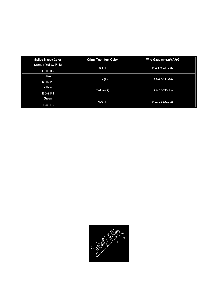
4. Select the proper DuraSeal splice sleeve according to the wire size. Refer to the above table at the beginning of the repair procedure for the color
coding of the DuraSeal splice sleeves and the crimp tool nests.
5. Use the Splice Crimp Tool from the J-38125 in order to position the DuraSeal splice sleeve in the proper color nest of the Splice Crimp Tool.
The crimp tool has three nests, (1) is for the salmon and green splice sleeve, (2) is for the blue splice sleeve, and (3) is for the yellow splice sleeve.