
Escalade AWD V8-6.2L (2009)
Failure to follow the procedure exactly as written may result in serious injury or death.
Caution: Refer to Test Probe Caution (See: Service Precautions/Vehicle Damage Warnings/Test Probe Caution).
The following procedure measures the voltage at a selected point in a circuit.
1. Disconnect the electrical harness connector for the circuit being tested, if necessary.
2. Enable the circuit and/or system being tested. Use the following methods:
*
Turn ON the ignition, with the engine OFF.
*
Turn ON the engine.
*
Turn ON the circuit and/or system with a scan tool in Output Controls.
*
Turn ON the switch for the circuit and/or system being tested.
3. Select the V (AC) or V (DC) position on the DMM.
4. Connect the negative lead of the DMM to a good ground.
5. Connect the positive lead of the DMM to the point of the circuit to be tested.
6. The DMM displays the voltage measured at that point.
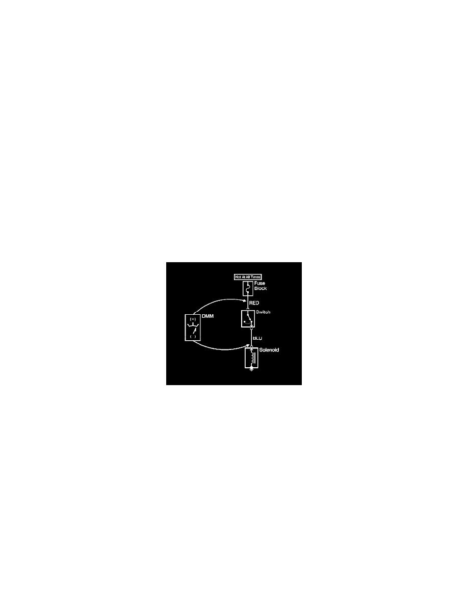
Measuring Voltage Drop
Measuring Voltage Drop
Caution: Refer to Test Probe Caution (See: Service Precautions/Vehicle Damage Warnings/Test Probe Caution).
The following procedure determines the difference in voltage potential between 2 points.
1. Set the rotary dial of the DMM to the V (DC) position.
2. Connect the positive lead of the DMM to one point of the circuit to be tested.
3. Connect the negative lead of the DMM to the other point of the circuit.
4. Operate the circuit.
5. The DMM displays the difference in voltage between the 2 points.
Probing Electrical Connectors
Probing Electrical Connectors
Danger: This procedure should not be performed on high voltage circuits. Performing this procedure on high voltage circuits may result in
serious injury or death.
Note: Always be sure to reinstall the connector position assurance (CPA) and terminal position assurance (TPA) when reconnecting connectors or
replacing terminals.
Front probe
Disconnect the connector and probe the terminals from the mating side (front) of the connector.
Caution: Do not insert test equipment probes (DMM etc.) into any connector or fuse block terminal. The diameter of the test probes will deform most
terminals. A deformed terminal will cause a poor connection, which will result in a system failure. Always use the J-35616 GM-Approved Terminal Test