
Escalade ESV AWD V8-6.2L (2007)
Information Bus: Symptom Related Diagnostic Procedures
A Symptoms - Data Communications
SYMPTOMS - DATA COMMUNICATIONS
IMPORTANT: The following steps must be completed before using the symptom tables.
1. Perform the Diagnostic System Check - Vehicle before using the symptom tables in order to verify that all of the following are true:
-
There are no DTCs set.
-
The control modules can communicate via the serial data links. See: Testing and Inspection/Initial Inspection and Diagnostic
Overview/Diagnostic Starting Point - Vehicle
2. Review the system operation in order to familiarize yourself with the system functions. Refer to Data Link Communications Description and
Operation.
Visual/Physical Inspection
-
Inspect for aftermarket devices which could affect the operation of the systems. Refer to Checking Aftermarket Accessories See: Testing and
Inspection/Component Tests and General Diagnostics.
-
Inspect the easily accessible or visible system components for obvious damage or conditions which could cause the symptom.
Intermittent
Faulty electrical connections or wiring may be the cause of intermittent conditions. Refer to Testing for Intermittent Conditions and Poor Connections
See: Testing and Inspection/Component Tests and General Diagnostics.
Symptom List
Refer to a symptom diagnostic procedure from the following list in order to diagnose the symptom:
-
Scan Tool Does Not Power Up
-
Scan Tool Does Not Communicate with High Speed GMLAN Device
-
Scan Tool Does Not Communicate with Low Speed GMLAN Device
Scan Tool Does Not Communicate with High Speed GMLAN Device
SCAN TOOL DOES NOT COMMUNICATE WITH HIGH SPEED GMLAN DEVICE
DIAGNOSTIC FAULT INFORMATION
Perform the Diagnostic System Check - Vehicle prior to using this diagnostic procedure See: Testing and Inspection/Initial Inspection and Diagnostic
Overview/Diagnostic Starting Point - Vehicle.
CIRCUIT/SYSTEM DESCRIPTION
Modules connected to the high speed GMLAN serial data circuits monitor for serial data communications during normal vehicle operation. Operating
information and commands are exchanged among the modules when the ignition switch is in any position other than OFF. The high speed GMLAN
serial data circuits must be operational for the vehicle to start due to body control module (BCM) and engine control module (ECM)/powertrain
control module (PCM) communications. The theft deterrent module and ECM/PCM exchange information using the BCM as the gateway module
allowing communication between the high and low speed serial data busses. The low speed GMLAN serial data circuit must also be operational for
vehicle starting.
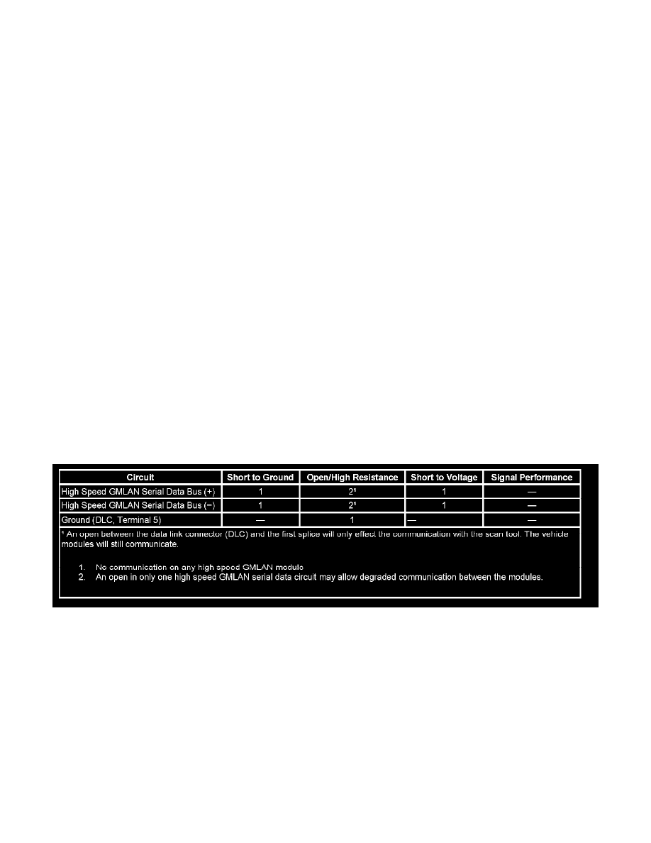
DIAGNOSTIC AIDS
-
Use the Data Link References to identify the high speed GMLAN serial data modules.
-
This test is used for a total high speed GMLAN communication failure. If only 1 module is not communicating and sets no DTC, ensure that the
vehicle is equipped with the module, then use DTC U0100-U0299 for diagnostics.
-
An open in the DLC ground circuit terminal 5 will allow the scan tool to operate to set up the vehicle on the tool and then not communicate with