
Escalade ESV AWD V8-6.2L (2007)
the other row of terminal cavities in the connector. The second design has terminals cavities that are closer together (2.54 mm centerline) and aligned
vertically. One other way to identify the second design is the thin strip of material that runs along the outside of the cavities.
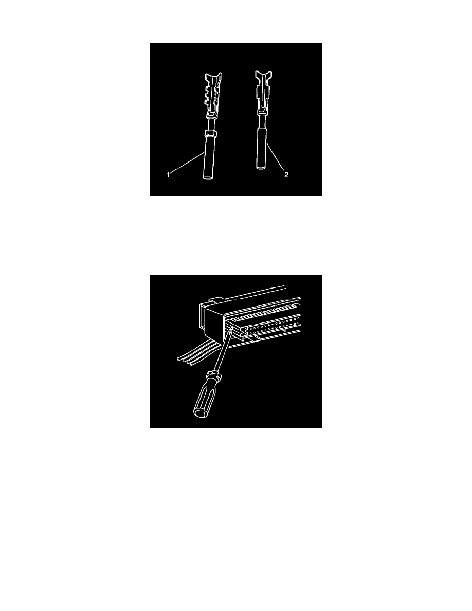
IMPORTANT: There are 2 styles of Micro-Pack 100W terminals which are very similar. Ensure that you have the correct terminal before crimping
the new terminal to the wire. The first design connector uses the longer terminal (1) that has a raised area in front of the recess in the terminal. The
second design connector uses the shorter terminal without the raised area.
Follow the steps below in order to remove terminals from Micro-Pack 100W connectors. Some Micro-Pack 100W connector disassembly procedures
will vary. Use this procedure as a guide.
1. Disconnect the connector from the component.
2. Locate the nose piece locking tabs that are positioned on the side of the connector nose piece. The connector nose piece acts as a terminal positive
assurance (TPA) and may be referred to as such.