
Escalade EXT AWD V8-6.2L (2009)
Connector End View Reference
Component Connector End Views (See: Diagrams/Connector Views)
Description and Operation
*
Cruise Control Description and Operation (See: Description and Operation)
*
Indicator/Warning Message Description and Operation (See: Instrument Panel, Gauges and Warning Indicators/Description and
Operation/Indicator/Warning Message Description and Operation)
Electrical Information Reference
*
Circuit Testing (See: Testing and Inspection/Component Tests and General Diagnostics)
*
Connector Repairs (See: Testing and Inspection/Component Tests and General Diagnostics)
*
Testing for Intermittent Conditions and Poor Connections (See: Testing and Inspection/Component Tests and General Diagnostics)
*
Wiring Repairs (See: Testing and Inspection/Component Tests and General Diagnostics)
Scan Tool Reference
Control Module References (See: Testing and Inspection/Programming and Relearning) for scan tool information
Circuit/System Verification
Ignition ON, with a scan tool perform the Lamp Test for the instrument panel cluster (IPC) and observe the cruise control indicator.
If the cruise control indicator illuminates during the test, replace the ECM.
If the cruise control indicator does not illuminates during the test or remains illuminated at all times, replace the IPC.
Repair Instructions
Perform the Diagnostic Repair Verification (See: Powertrain Management/Computers and Control Systems/Testing and Inspection/Diagnostic Trouble
Code Tests and Associated Procedures/Verification Tests and Procedures) after completing the diagnostic procedure.
Control Module References (See: Testing and Inspection/Programming and Relearning) for ECM or IPC replacement, setup, and programming
Cruise Control Malfunction
Cruise Control Malfunction
Diagnostic Instructions
*
Perform the Diagnostic System Check - Vehicle (with HP2) (See: Testing and Inspection/Initial Inspection and Diagnostic Overview/Diagnostic
System Check - Vehicle)Diagnostic System Check - Vehicle (without HP2) (See: Testing and Inspection/Initial Inspection and Diagnostic
Overview/Diagnostic System Check - Vehicle) prior to using this diagnostic procedure.
*
Review Strategy Based Diagnosis (See: Testing and Inspection/Initial Inspection and Diagnostic Overview/Strategy Based Diagnosis) for an
overview of the diagnostic approach.
*
Diagnostic Procedure Instructions (See: Testing and Inspection/Initial Inspection and Diagnostic Overview/Diagnostic Procedure Instructions)
provides an overview of each diagnostic category.
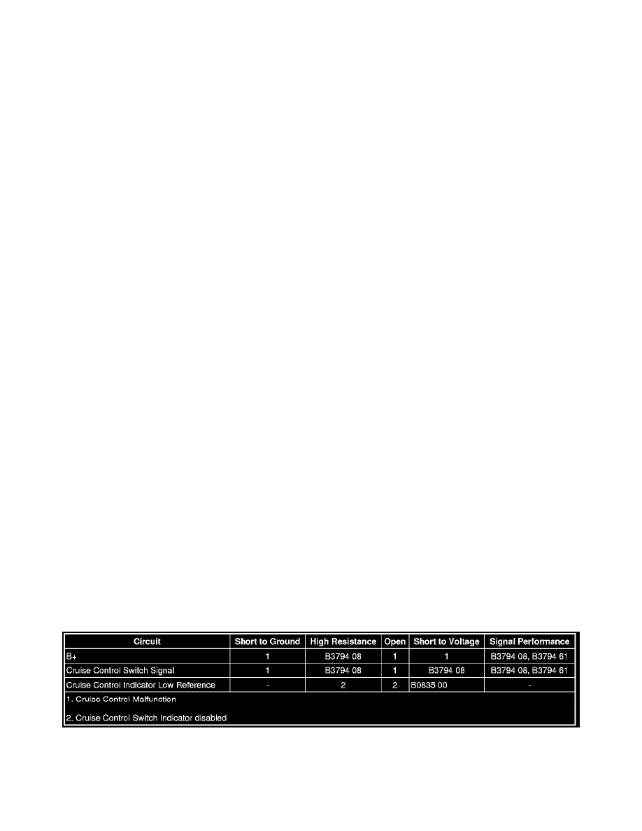
Diagnostic Fault Information
Circuit/System Description
The body control module (BCM) supplies battery voltage to the cruise control switch. The cruise control switch signal is an input to the BCM. The BCM
monitors the cruise control switch signal circuit in order to detect when the driver has requested to perform a cruise control function. The BCM detects a
specific voltage signal on the cruise control switch signal circuit when a switch is applied.