
Escalade EXT AWD V8-6.2L (2009)
Auxiliary Power Outlet: Symptom Related Diagnostic Procedures
Power Outlet Receptacle Inoperative
Power Outlet Receptacle Inoperative
Diagnostic Instructions
*
Perform the Diagnostic System Check - Vehicle (without HP2) (See: Testing and Inspection/Initial Inspection and Diagnostic
Overview/Diagnostic System Check - Vehicle) prior to using this diagnostic procedure.
*
Review Strategy Based Diagnosis (See: Testing and Inspection/Initial Inspection and Diagnostic Overview/Strategy Based Diagnosis) for an
overview of the diagnostic approach.
*
Diagnostic Procedure Instructions (See: Testing and Inspection/Initial Inspection and Diagnostic Overview/Diagnostic Procedure Instructions)
provides an overview of each diagnostic category.
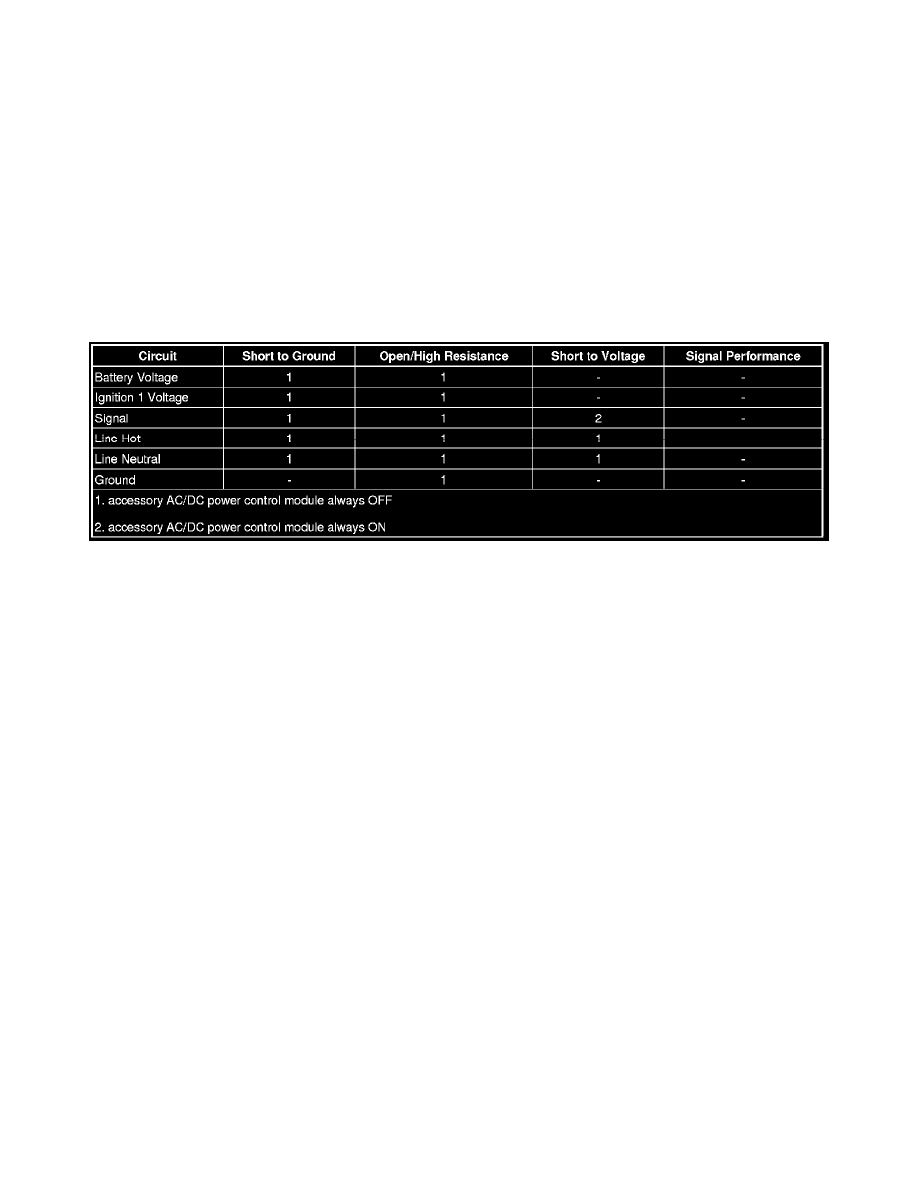
Diagnostic Fault Information
Circuit/System Description
The accessory AC/DC power control module converts 12 volt direct current (DC) battery voltage to 110-120 volt alternating current (AC) in order to
operate AC powered devices. The accessory AC/DC power control module provides up to 150 watts of power. The accessory AC/DC power control
module is connected to a chassis ground circuit and receives fuse protected battery voltage.
The accessory power outlet has an internal switch, that detects when an AC powered device is plugged into the outlet. When the ignition is ON and a 120
volt AC powered device is plugged into the accessory power outlet, the normally-open switch in the accessory power outlet, closes. When the accessory
AC/DC power control module detects the voltage from the accessory power outlet switch, the inverter module begins to supply 110-120 volts AC to the
accessory power outlet after a 1.5 second delay.
Diagnostic Aids
A household 120 volt duplex receptacle outlet tester should not be used to diagnose this system. The tester will indicate an open ground, which is a
normal condition.
Reference Information
Schematic Reference
Cigar Lighter/Power Outlet Schematics (See: Diagrams/Electrical Diagrams)
Connector End View Reference
Component Connector End Views (See: Diagrams/Connector Views)
Description and Operation
Power Outlets Description and Operation (See: Description and Operation)
Electrical Information Reference
*
Circuit Testing (See: Testing and Inspection/Component Tests and General Diagnostics)
*
Connector Repairs (See: Testing and Inspection/Component Tests and General Diagnostics)
*
Testing for Intermittent Conditions and Poor Connections (See: Testing and Inspection/Component Tests and General Diagnostics)
*
Wiring Repairs (See: Testing and Inspection/Component Tests and General Diagnostics)
Circuit/System Verification