
Fleetwood V8-368 6.0L VIN 9 FI (1982)
There are four basic types of brake warning lamp switches as shown in Figs. 4 through 7 and usually they form a common electrical circuit with the
brake warning lamp.
When a pressure differential occurs between the front and rear brake systems, the valves will shuttle toward the side with the low pressure.
As shown in Fig. 4, movement of the differential valve forces the switch plunger upward over the tapered shoulder of the valve to close the switch
contacts and light the dual brake warning lamp, signaling a brake system failure.
In Fig. 5, the valve assembly consists of two valves in a common bore that are spring loaded toward the centered position. The spring-loaded switch
contact plunger rests on top of the valves in the centered position (right view). When a pressure differential occurs between the front and rear brake
systems, the valves will shuttle toward the side with the low pressure. The spring-loaded switch plunger is ``triggered'' and the ground circuit for the
warning lamp is completed, lighting the lamp (left view).
In Fig. 6, as pressure falls in one system, the other system's normal pressure forces the piston to the inoperative side, contacting the switch terminal,
causing the warning lamp on the instrument panel to glow.
Fig. 7 shows the switch mounted directly in the master cylinder assembly. Whenever there is a specified differential pressure, the switch piston will
activate the brake failure warning switch and cause the brake warning lamp to glow.
Some early production 1984 Eldorados and Sevilles may falsely indicate a low vacuum condition as a result of brake light illumination during hard or
repeated brake pedal application. This may be caused by the incorrect usage of 1983 low vacuum switches on 1984 models. The correct switch for 1984
and later models can be distinguished from the earlier 1983 switch by looking directly at the portion of the switch which sits inside the vacuum chamber
of the brake booster. This switch, Fig. 8, uses a silver center plug. The 1983 switch, Fig. 9, has an open port.
If the earlier 1983 switch is installed on a later models, replace switch with vacuum switch part No. 18010278. To aid in removal of the low
vacuum switch, ensure vacuum booster vacuum reserve is exhausted, by repeatedly depressing brake pedal until a stiff, hard pedal is obtained.
Lightly apply silicone lubricant or equivalent onto switch during installation.
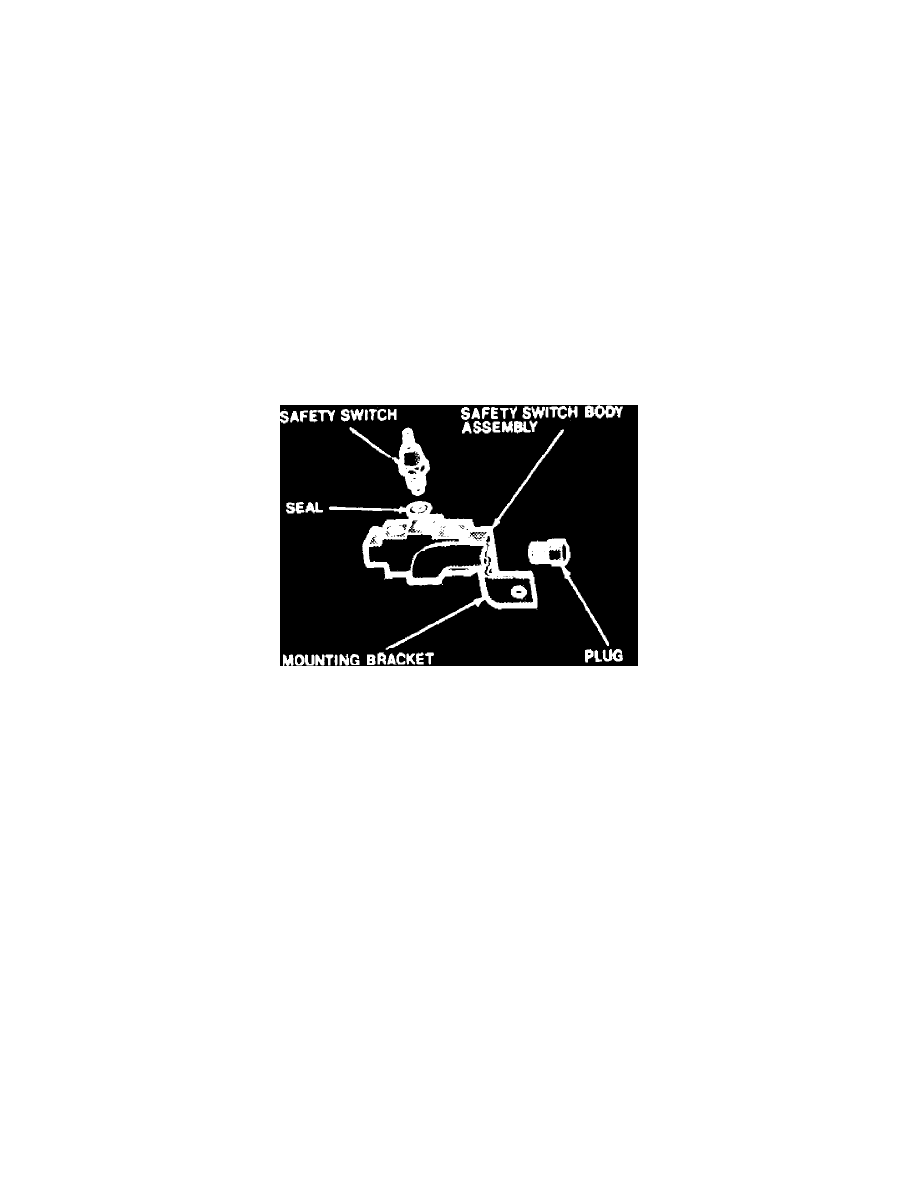
Fig. 10 Typical pressure valve and brake warning lamp switch.
Testing Warning Lamp System
If the parking brake lamp is connected into the service brake warning lamp system, the brake warning lamp will flash only when the parking brake is
applied with the ignition turned ON. The same lamp will also glow should one of the two service brake systems fail when the brake pedal is applied.
To test the system, turn the ignition on and apply the parking brake. If the lamp fails to lamp, inspect for a burned out bulb, disconnected socket, a
broken or disconnected wire at the switch.
An exterior view of one of these switches is shown, Fig. 10.. They are usually mounted on the left frame side rail or on the brake pedal bracket.
To test the brake warning system, raise the car and open a wheel bleeder valve while a helper depresses the brake pedal and observes the warning
lamp on the instrument panel. If the bulb fails to light, inspect for a burned out bulb, disconnected socket, or a broken or disconnected wire at the switch.
If the bulb is not burned out, and the wire continuity is proven, replace the brake warning switch.