
Fleetwood Brougham V8-307 5.0L (1989)
2.
Remove close out panel(s) and glove box as required to gain access to the circuits shown in the applicable wiring diagram. Refer to the appropriate
Service Information Manual for component location and service procedures.
3.
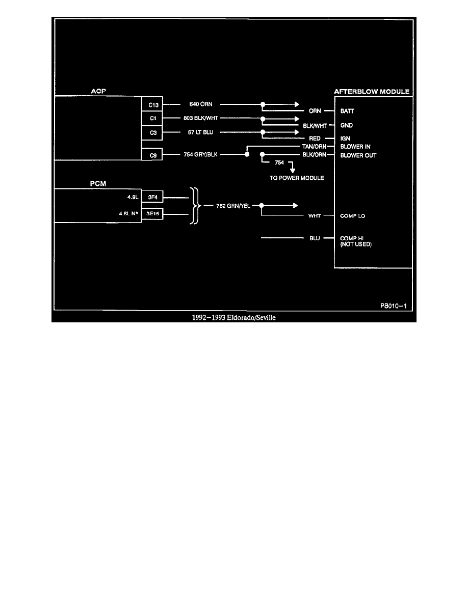
Splice, clip, and solder (refer to Section 8A of the appropriate Service Information Manual for splicing instructions) the various leads to the
afterblow module wiring harness with the circuits shown in the corresponding wiring diagram on the following pages. Disconnect the wiring
harness from the afterblow module and connect the black/white ground lead first before completing the remaining splices. Since a majority of
circuits to be spliced are low current circuits, care should be taken to assure that the splices are completed and soldered correctly.
4.
Test operation of afterblow as follows:
a.
Start vehicle.
b.
Turn A/C system on to engage compressor.
c.
Connect jumper wire to apply battery voltage to open position pin H (green wire) of afterblow module for at least 30 seconds with
compressor engaged.
d.
Turn vehicle ignition off.
e.
Blower should come on after approximately 10 seconds for one second and then go off.
f.
Disconnect jumper wire from pin H (green wire).
5.
Add foam insulation as necessary to ensure rattle-free installation of the afterblow module.
NOTE:
The afterblow module affects aftermarket and Goodwrench theft alarm systems. Cycling the blower motor with key off could trigger alarms that
sense battery voltage changes or current drain.
Procedure D (Enabling Afterblow Mode)