
Fleetwood Brougham V8-307 5.0L (1989)
Transmission Position Switch/Sensor: Testing and Inspection
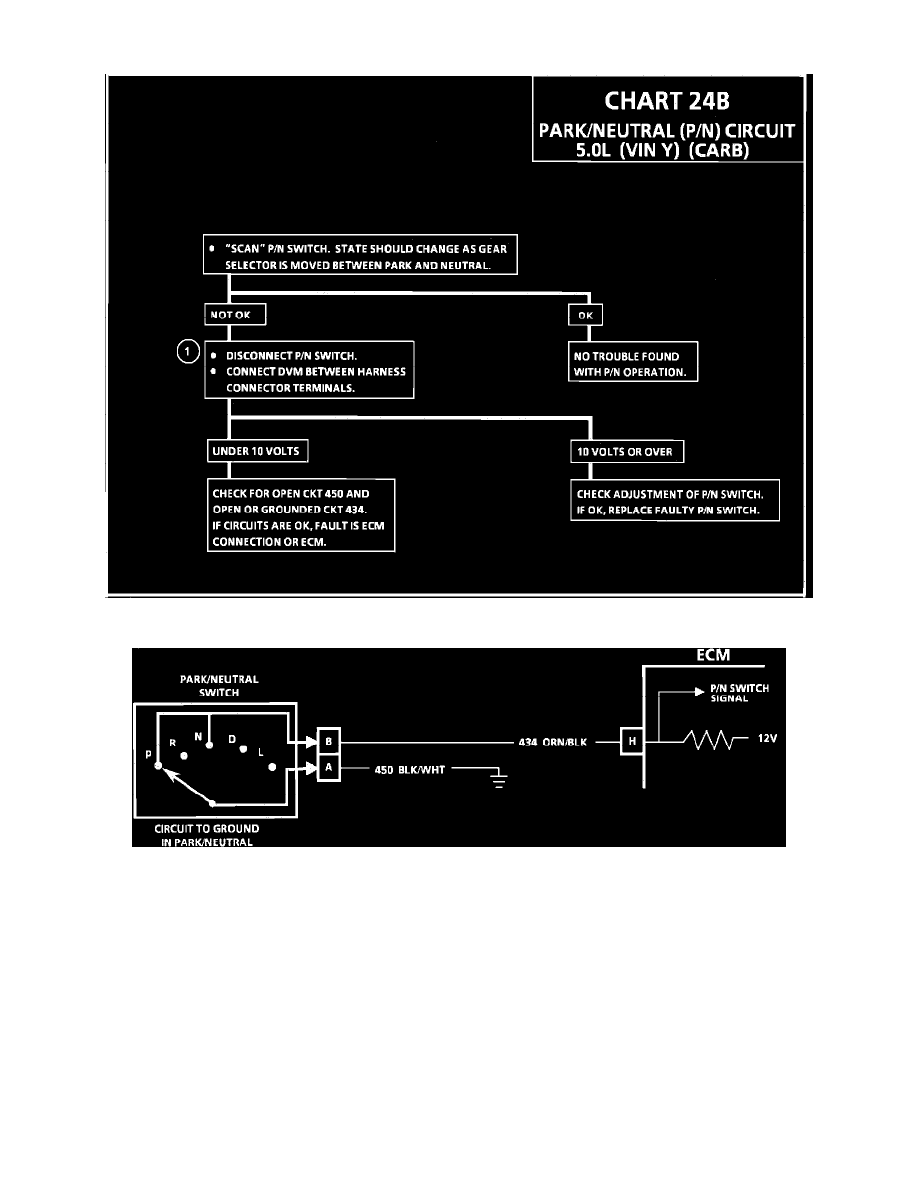
Chart 24B "Park/Neutral (P/N) Circuit
Wiring Diagram - Park/Neutral (P/N) Circuit
CHART 24B
PARK NEUTRAL (P/N) CIRCUIT
Circuit Description:
The P/N switch is connected to the transmission gear selector. The switch is closed when the gear selector is in park or neutral and open for all other
ranges. One side of the switch is connected to the ECM, which supplies a buffered 12 volts. The other side of the switch is connected to ground. The P/N
switch state is an input to the ECM. Low voltage at ECM terminal "H" indicates the transmission is in park or neutral range while high voltage indicates
it is in a drive range or reverse.
Test Description: Number below refers to circled number on the diagnostic chart.
1.
This step separates a faulty switch or switch adjustment from a faulty electrical circuit or ECM. Normal voltage across the terminals of the