
Fleetwood FWD V8-252 4.1L (1986)
Whenever a vehicle subject to this campaign is taken into used car inventory, dealers are to take the steps necessary to be sure the campaign correction
has been made before reselling the vehicle.
In addition, dealers are to perform the campaign on all affected vehicles as they are brought in for any kind of service.
PARTS INFORMATION
The parts required to complete this campaign should be obtained from the Parts Distribution Centers of General Motors Service Parts Operations
(GMSPO). A description is provided below:
Quantity Required
Part Number
Description
Per Vehicle
25530882
Pressure (Warning) Switch
1
25528401
Hydraulic Pump & Motor
1
25525848
Pump Motor Relay
1
12004011
30 Amp Fuse
2
*NOTICE: It is anticipated that most cars will require a pressure (warning) switch, but that less than 20% will require a hydraulic pump and motor. All
cars will require relay and fuses. Please adjust your orders accordingly for the hydraulic pump and motor.
If there is difficulty obtaining these parts using normal ordering procedures, dealers may place a C.I.O. using advise Code "2" with no special instruction
code. The parts may also be ordered on a V.I.P. order; however, unless prior zone approval is obtained, dealers will be required to absorb any surcharge
involved under the V.I.P. system.
If any problems are encountered in obtaining these parts, please follow the three step procedure as stated in the GM Parts Emergency Order Follow-up
Procedure (Refer to GM Parts Policy & Procedure Manual, Section IV, pages 32 and 33, August 1984 Edition).
Service Procedure
1.
Raise hood, install fender covers. Leave ignition key in OFF position. Disconnect negative battery cable from battery.
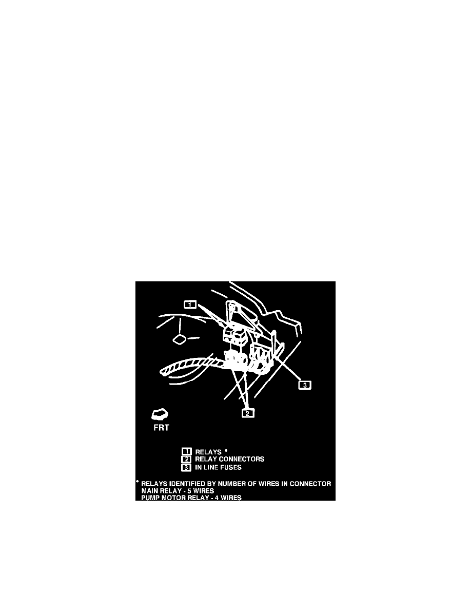
RELAYS AND FUSES LOCATIONS - ILLUSTRATION 1
2.
Replace the ABS pump motor relay, and both the ABS pump motor 30 amp fuse and the ABS main 30 amp fuse. The pump motor relay will have
four wires in its connector. Relay and fuses are located on the left front of dash behind the strut tower (see illustration 1).
CAUTION: Relay must be reinstalled on bracket with connector at bottom to prevent water entry. If relay bracket mounting is disturbed, bracket
must be resecured to front of dash.
3.
Visually inspect hydraulic pump and motor housing for any evidence of brake fluid seepage below the pressure switch. If any components require
replacement, care should be taken to prevent brake fluid spillage onto the motor.