
Fleetwood FWD V8-252 4.1L (1986)
Cabin Temperature Sensor / Switch: Customer Interest
Climate Control - Temperature Drift
Bulletin No. T
87-103
File in Group
1
Number
34
Corp. Ref. No.
711202
Date
May '87
SUBJECT:
CLIMATE CONTROL TEMPERATURE DRIFT
MODELS AFFECTED: 1985-1987 DE VILLES AND FLEETWOODS
Some 1985-1987 De Ville and Fleetwood vehicles may exhibit A/C - heater temperature drift. This condition may be caused by insufficient air flow over
the "in-car" temperature sensor, which may be caused by one or more of the following items:
1.
Disconnected or kinked aspirator hose.
2.
"In-car" temperature sensor opening in the upper I/P cover restricted by excess vinyl material.
3.
Cadillac script restricting air flow over the in-car temperature sensor.
4.
"In-car" sensor mis-aligned or touching sensor housing.
To repair this condition, complete the following steps:
1.
With the climate control system operating at "high blower", right A/C duct off, observe if smoke is drawn around the Cadillac script at the
right side of the upper I/P cover. If the smoke does not appear to be drawn into the sensor opening around the Cadillac script, insufficient
aspirator operation may be suspected.
2.
Remove the upper I/P cover as outlined in Section 8C of the Cadillac Service Information Manual. During the removal operation, inspect the
aspirator hose for disconnects and/or kinks which may restrict aspirator operation. If a disconnected or kinked hose is found, repair and
re-test as above.
3.
Remove the "in-car" temperature sensor from the upper I/P cover and inspect the thermistor alignment, the sensor should be centered in the
hose opening and not touching any portion of the sensor housing.
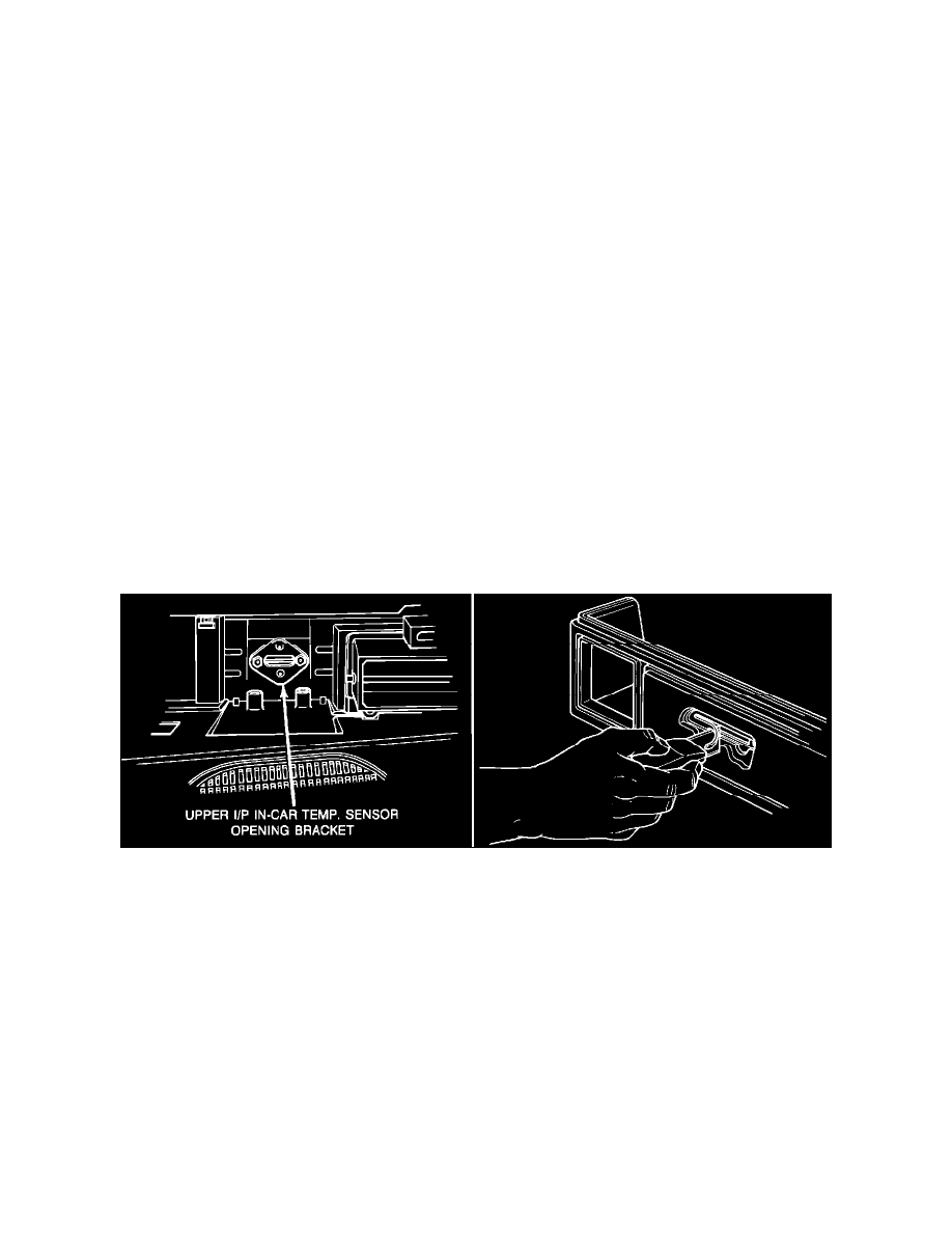
FIGURE 1 - I/P Cover And Assembly
4.
Remove the two fasteners which retain the Cadillac script to the upper I/P cover. Inspect the sensor opening for vinyl/foam material
restricting the opening. Vinyl/foam material should be trimmed to the size as indicated by the metal reinforcement attached to the upper back
of the I/P cover (Figure 1). If the vinyl/foam material is restricting the sensor opening, from the front side of the upper I/P cover trim the
material from the opening with a sharp knife or suitable tool using the metal reinforcement as a guide (Figure 1). Place the Cadillac script in
the opening and observe the clearance between the back of the script and the I/P cover. If the clearance is less than 1/16", shim the script
studs to obtain the proper clearance and install the script fasteners. Do not over torque the script fasteners.