
Fleetwood FWD V8-252 4.1L (1986)
Speed Sensor And Buffer Amplifier Circuit
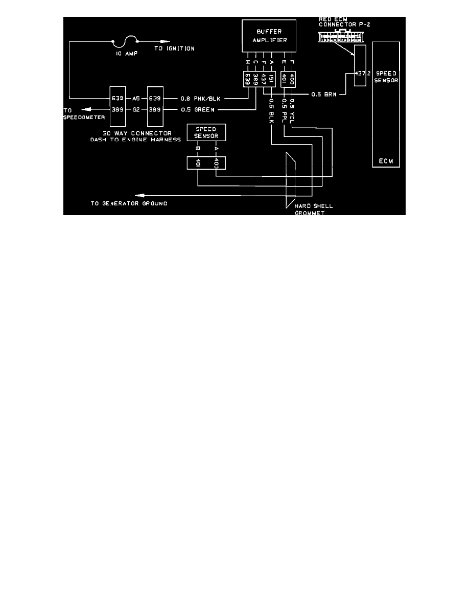
The standard speedometer cluster is quartz electrically controlled with a conventional swing needle indicator. A speed sensor located at the transmission
sends electrical pulses to a speed sensor buffer amplifier. The buffer amplifier sends amplified electrical pulses to the quartz mechanism in the
speedometer, which converts it to a mechanical movement. The odometers are driven by a stepper motor that is controlled by the same electrical pulses
that are sent by the speed sensor buffer amplifier.
The speedometer circuit consists of a driver and logic IC (integrated circuit) chips, a crystal oscillator, and some discrete electrical components. These
components, diodes, resistors and capacitors, act as buffers, power surge suppressors and EMI protection by limiting and filtering the various input and
output signals.
The Vehicle Speed Sensor (VSS) is a permanent magnet generator mounted in the transmission, designed to replace the transmission speedometer drive
gear and sleeve. The purpose of the VSS is to provide an AC speed signal that is proportional to the vehicle speed at a rate of 4004 pulses per mile. This
AC signal is transmitted to the buffer amplifier, filtered and conditioned, then transmitted to the speedometer circuitry.