
Fleetwood FWD V8-252 4.1L (1986)
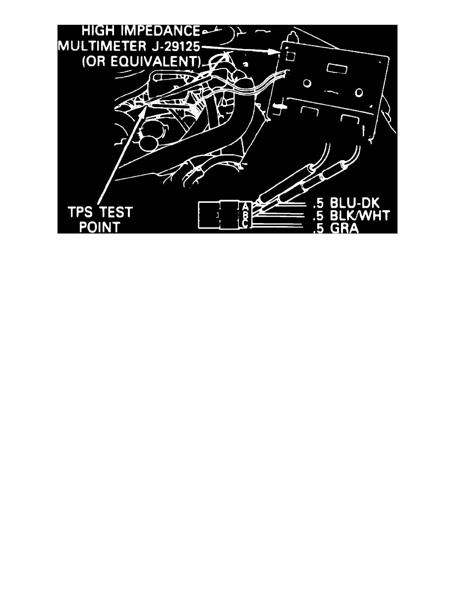
Fig. 101 TPS harness test point
MINIMUM AIR, THROTTLE POSITION SENSOR (TPS) & IDLE SPEED CONTROL (ISC) MOTOR, ADJUST
1.
Turn ignition on, then enter diagnostics. Note all trouble codes displayed between the time .1.8.8 is displayed and .7.0 is displayed. Diagnose any
trouble codes by referring to appropriate diagnostic procedures before continuing to step 2.
2.
Perform switch tests as previously described. Diagnose any trouble codes which do not pass by referring to appropriate diagnostic procedure.
3.
Remove air cleaner and plug Thermactor, then run engine until normal operating temperature is reached. Check ignition timing with A/C off and
adjust as necessary.
4.
Turn off all electrical accessories and ensure cooling fans are not running, then shift transaxle to Park and center steering wheel. Retract ISC motor
plunger by applying external power with tester tool No. J-34025 or equivalent, or by using jumper harness procedure as follows:
a. Disconnect ISC electrical connector and connect jumper harness to ISC, Figs. 98 and 99.
b. Connect jumper wire at ISC terminal C to 12 volt power source.
c. Apply finger pressure to ISC plunger to close throttle switch, then connect jumper wire at ISC terminal D to ground until plunger retracts
fully and stops. Remove ground wire immediately after plunger retracts and stops to avoid damaging the motor. Also, it is important
to apply pressure to plunger when retracting to prevent clashing and binding of the internal gears.
d. With ISC plunger fully retracted, ensure plunger does not contact throttle lever. If contact is noted, turn plunger in with pliers until it no
longer contacts lever.
5.
Exit diagnostics by depressing Auto button, then depress Off button for ten seconds to de-energize A/C clutch. Enter diagnostics and ensure
Outside Temp light is not lit.
6.
Display parameter .1.1 and observe engine speed at minimum air. If displayed engine speed is 40-50, proceed to step 8. If engine speed is not
40---50, proceed to step 7.
7.
Connect tachometer to engine and adjust throttle stop screw to obtain 450 RPM. If speed cannot be adjusted to 450 RPM, ensure throttle is not
held off minimum stop screw due to binding linkage or interference with ISC motor plunger. Also, check for vacuum leaks at throttle body, intake
manifold, vacuum fittings and hoses and repair as necessary.
8.
Turn ignition on, enter diagnostics and display parameter .0.1, then open throttle and let it snap fully shut against throttle stop screw. If value of
parameter .0.1 is 0, proceed to step 2. If value is not 0, disconnect TPS electrical connector and measure voltage between terminals B and C, Fig.
100.
9.
Connect a digital voltmeter to TPS harness test point, Fig. 101, as follows:
a. Turn ignition on, then connect voltmeter positive lead to pin A.
b. Connect voltmeter negative lead to pin B and set voltmeter to the 2 volt DC scale.
10.
If TPS voltage is within .05 volts of value shown in Fig.100, proceed to step 12.
11.
If voltage reading is not within specifications, loosen TPS attaching screws just enough to allow rotation of the sensor. With throttle fully shut
against throttle stop screw, turn sensor until voltage is within specifications, then retighten attaching screws. Do not overtighten TPS screws.
After tightening screws, recheck voltmeter reading.
12.
With throttle fully shut against throttle stop screw and ISC motor fully retracted, adjust gap between ISC motor plunger and throttle lever to
.150-.160 inch by turning plunger adjusting screw as necessary. If gap measures .140-.170 inch, no adjustment is needed.
13.
Extend ISC plunger by connecting ISC terminal D to 12 volt power source, then momentarily grounding terminal C, as many times as necessary,