
Fleetwood FWD V8-273 4.5L (1988)
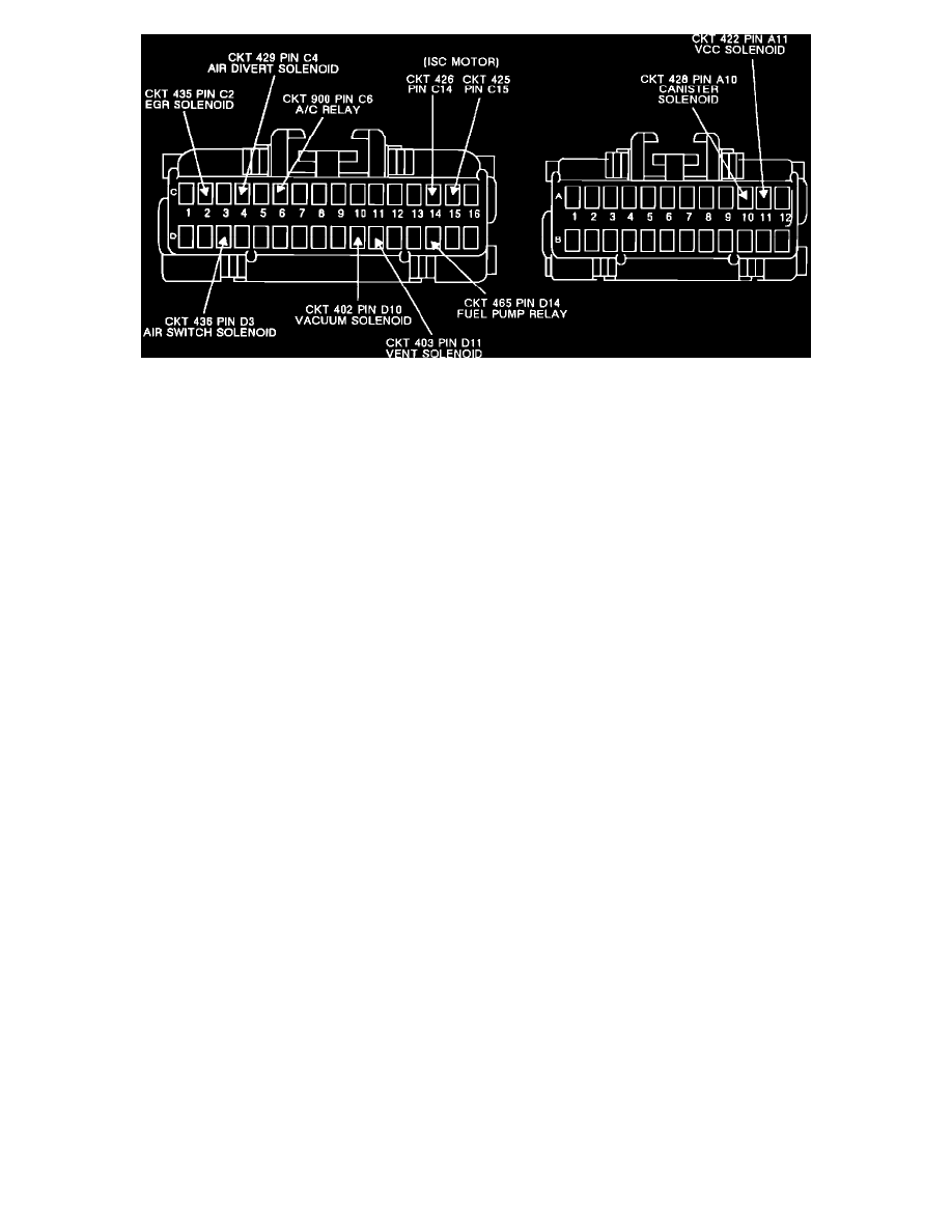
ECM Connector View
DESCRIPTION:
Prior to replacing an ECM, the vehicle must be tested for:
1.
Poor connector terminal to ECM contact.
2.
Direct short to battery voltage on an ECM ground circuit.
3.
Shorted solenoids or relays. If a short is found, the circuit must be repaired prior to replacing the ECM to prevent repeat ECM failures.
NOTES ON FAULT TREE:
1.
Check for poor terminal contact due to weak or dirty ECM terminals. Remove suspected terminals to inspect, replace if broken or dirty. If coolant
is present at the ECM connector, replace coolant sensor, coolant sensor connector, and the coolant sensor signal and ground wires. Also, replace
ECM connector terminal and blow coolant out of harness. Clean ECM connector with alcohol or spray contact cleaner and replace ECM.
2.
Checking for a short to ignition or shorted solenoid or relay. All terminals must be tested since several are connected together internally in the
ECM. A short in one circuit may cause another circuit in the ECM to be inoperative. An example might be that the VCC solenoid shorted can
cause both VCC to be inoperative and the EGR to be enabled at all times. Any circuit testing below 20 ohms is shorted and should be diagnosed
for the cause of the short.
3.
Check ISC circuit (EXTEND/RETRACT) for shorted to ground or shorted together. Normal resistance for an ISC motor circuit is 4-100 ohms.
Checking Control Module For Bad Solder Joints
Some control modules may have problems due to cracked solder joints on the circuit board. These internal control module problems can cause the
following symptoms:
^
Failure to start or vehicle is stalling.
^
The "CHECK ENGINE" "SERVICE ENGINE SOON" or "MALFUNCTION INDICATOR" light will flash or light up, but no trouble codes
will be present.
^
Vehicle instrument panel displays may be inoperative.
^
The control module may or may not communicate with the scanner.
^
Other intermittent driveability problems.
Incorrect PROM or MEMCAL removal and replacement can create solder joint problems or aggravate an existing condition. See PROM or
MEMCAL INSTALLATION for proper procedures.
If a solder joint problem results in a "hard" failure, normal test procedures will usually pinpoint a faulty control module. Many symptoms caused by poor
solder joints in the control module result in intermittent problems, but they may be hard to duplicate during troubleshooting. Control module's with
solder joint problems are sensitive to heat and vibration. You can check for these internal control module problems in either, or both, of the following
ways:
^
Remove the control module from its mounting bracket and extend it on the harness so that you can expose it to the vehicle heater ducts.
Alternatively, use flexible ducting to route air from the heater to the control module location. Then run the engine and operate the heater at
the "MAX HEAT" position. This exposes the control module to approximately 140°F.
^
With the engine running, tap on the control module several times with your hand or finger tips to simulate vehicle vibration.