
Fleetwood FWD V8-300 4.9L (1993)
To replace a damaged fusible link, Fig. 4, cut it off beyond the splice. Replace with a repair link. When connecting the repair link, strip wire and
use staking-type pliers to crimp the splice securely in two places. For more details on splicing procedures, see Diagnostic Aids/Connector and
Wire Repair. Use Crimp and Seal splices whenever possible.
To replace a damaged fusible link which feeds two harness wires, cut them both off beyond the splice. Use two repair links, one spliced to each
harness wire, Fig. 5.
Typical Electrical Repair
TYPICAL ELECTRICAL REPAIR
An open circuit is an incomplete circuit. Power cannot reach the load or reach ground. If a circuit is open, active components do not energize. A
short circuit is an unwanted connection between one part of the circuit and either ground or another part of the circuit. A short circuit causes a fuse
to blow or a circuit breaker to open.
SHORT CIRCUITS CAUSED BY DAMAGED WIRE INSULATION
^
Locate the damaged wire.
^
Find and correct the cause of the wire insulation damage.
^
For minor damage, tape over the wire. If damage is more extensive, replace the faulty segment of the wire.
Splicing Copper Wire Using Splice Clips
The Splice Clip (included in the GM J 38125-A Terminal Repair Kit) is a general purpose wire repair device. It may not be acceptable for
applications having special requirements such as moisture sealing.
Step 1: Open the Harness
If the harness is taped, remove the tape. To avoid wire insulation damage, use a sewing "seam ripper" to cut open the harness (available from
sewing supply stores). If the harness has a black plastic conduit, simply pull out the desired wire.
Step 2: Cut the Wire
Begin by cutting as little wire off the harness as possible. You may need the extra length of the wire later if you decide to cut more wire off to
change the location of a splice. You may have to adjust splice locations to make certain that each splice is at least 40 mm (1-1/2") away from other
splices, harness branches or connectors.
Step 3: Strip the Insulation
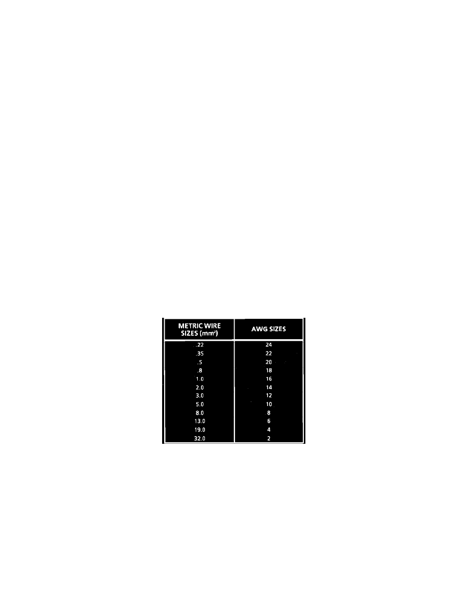
Fig. 6 Wire Size Conversion Table
When replacing a wire, use a wire of the same size as the original wire or larger. The schematics list wire size in metric units. See table, Fig. 6, for
the commercial (AWG) wire sizes that can be used to replace each metric wire size. Each AWG size is either equal to or larger than the equivalent
metric size. To find the correct wire size either find the wire on the schematic and convert the metric size to the AWG size, or use an AWG wire
gage. If you aren't sure of the wire size, start with the largest opening in the wire stripper and work down until a clean strip of the insulation is
removed. Be careful to avoid nicking or cutting any of the wires.
Step 4: Crimp the Wires