
Seville V8-273 4.5L (1989)
DFI ISC Circuit
DESCRIPTION:
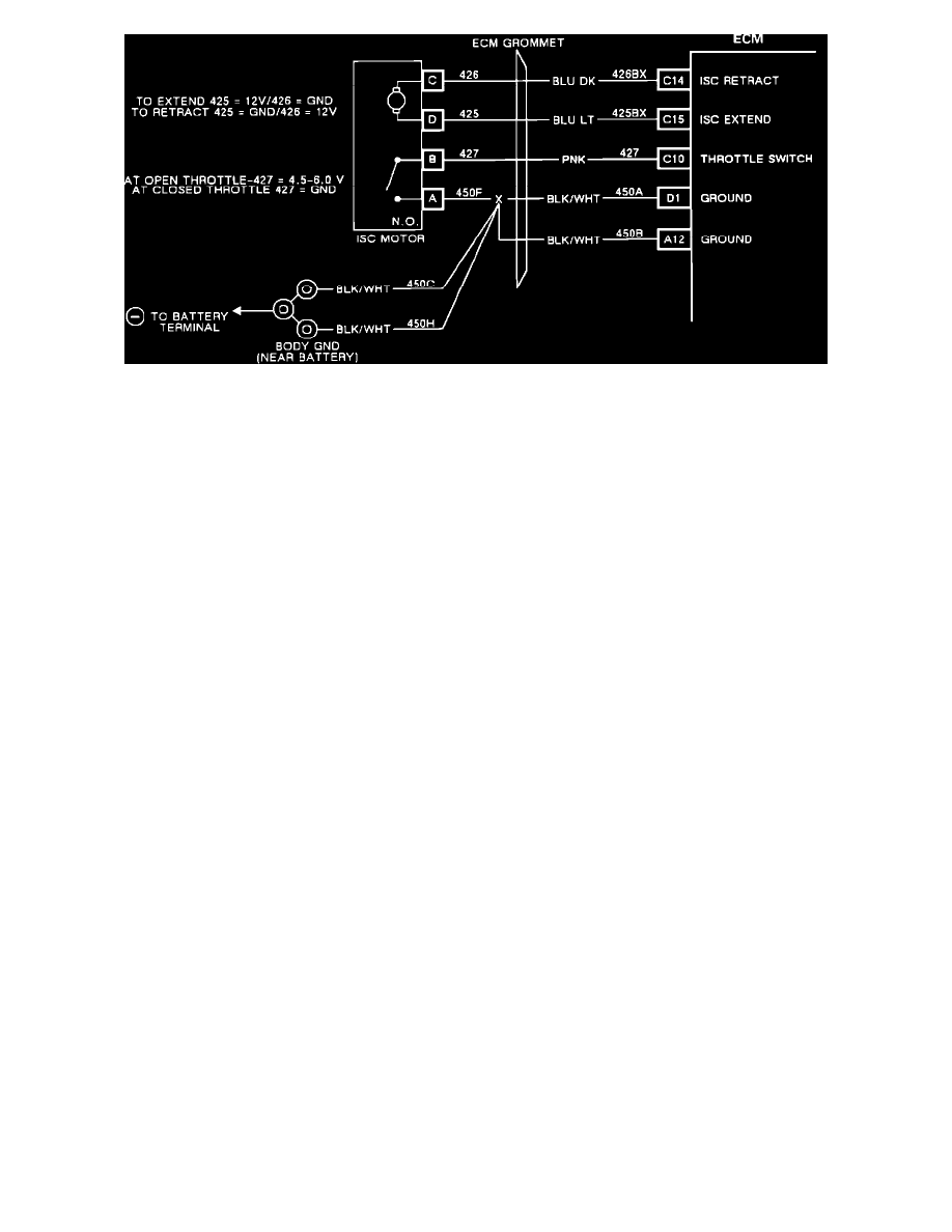
The Throttle Switch is part of the Idle Speed Control motor (ISC). Pin "B" of the four-way weather pack connector on the ISC is the throttle switch or
closed throttle input to the ECM. The ISC throttle switch contacts are normally open and are closed when the throttle linkage contacts the ISC plunger
(closed throttle, ISC in control of idle speed). The ECM sends a 5 volts signal to pin "B" of the ISC motor on CKT 427. When the throttle linkage rests
on the ISC plunger, the throttle switch contacts close, shorting ISC pin "B" to pin "A" (CKT 450 ground). The 5 volt signal from the ECM is grounded
at closed throttle, resulting in 0 volts at ECM pin C1O. When the throttle is opened, the throttle switch opens pin "B" CKT 427, resulting in 5 volts at
ECM pin C10. On the diagnostic display, "Hi" is an open switch, open throttle while "LO" is a closed switch, closed throttle (ISC in control of idle).
The ECM uses throttle switch input to determine when the ISC is in control of idle engine speed or throttle angle.
NOTES ON FAULT TREE:
1.
With ISC plunger depressed, status should be "LO", closed throttle. When the plunger is released, status should be "HI", open throttle.
2.
Check for throttle shaft, throttle plates binding, throttle spring weak or distorted, cruise and TV cables binding throttle linkage, TPS for proper
installation.
3.
When the ISC bottoms in the fully retracted position, the throttle switch will open. The ISC should be partially extended to control idle.
4.
Never connect a voltage source across pins "A" and "B" of ISC. Damage to throttle switch contacts will result.
5.
This step simulates the throttle switch shorting Pin "A" to Pin "B". If removing and replacing jumper causes switch to cycle, harness and ECM ire
OK; fault is in ISC motor connector or ISC motor.
6.
Checking for 5V reference signal to ISC.
7.
5V reference from ECM to ISC is open or shorted to ground.
8.
5V reference is OK - check for open CKT 45°F from ISC Pin "B" to ground.
NOTE ON INTERMITTENTS:
Check for binding throttle linkage due to TV, cruise or throttle cables, TPS mis-installed or throttle shaft binding.
Check for proper throttle return spring and throttle return spring installation.
Probe ECM C1O to ground with a voltmeter. Manipulate wiring and connectors at closed throttle and watch for 5.0 volts, indicating an open from C1O
to ground. Manipulate wiring and connectors at open throttle and watch for 0 volts, indicating short to ground on 427.