
Seville V8-273 4.5L (1989)
Wiper Motor: Description and Operation
Compound Wound Motor
Windshield wiper operation is controlled by a dash or steering column mounted switch. The wiper feed circuit is protected by a fuse which is located
in the fuse block on most models, or in an Inline fuse holder on some models with pulse wipers. A circuit breaker, integral with the motor brush holder,
protects the motor against overload. Pulse wipers, available on most models, use a variable resistor, a pulse control module, and/or a modified wiper
motor to provide a delay wipe mode.
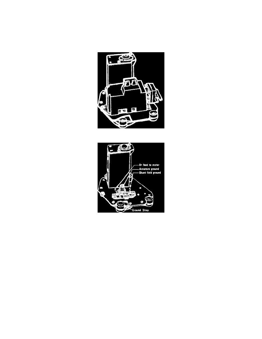
Fig. 1 Compound Wound Rectangular Windshield Wiper Motor. Shown W/washer Pump Installed
Fig. 2 Windshield Wiper Motor Electrical Connections. Compound Wound Rectangular Motor
RECTANGULAR MOTOR
The rectangular motor, Fig. 1, consists of an armature, brush plate assembly, field coils and a housing which is attached to a gear housing. The motor
electrical connections, park switch, and on some models a washer pump are also mounted on the gearbox. A gear on the commutator end of the armature
drives an intermediate gear and pinion assembly, which in turn drives the output shaft. A crank arm on the output shaft operates wipers through a pivot
link (transmission) assembly.
When ignition is on, battery voltage is supplied to motor terminal 2, Fig. 2. Current flows through the series field to a splice where it is divided, and
part passes through the armature and part through the shunt field. The armature and shunt field circuits are completed to ground through the wiper switch
, with motor speeds determined by resistance in the shunt field ground path.
Standard (Non-Pulse) Wiper Operation
Placing wiper switch in low position grounds motor terminals 1 and 3, Fig. 2, at the wiper switch. Shunt field current flows directly to ground through
terminal 3, armature current flows to ground through terminal 1 and the motor runs at low speed. Placing wiper switch in high position grounds terminal
1, but terminal 3 remains open. Armature current flows directly to ground through terminal 1, shunt field current flows to ground through a resistor
connected between terminals 1 and 3, and the motor runs at high speed due to the weakened shunt field.
When wiper switch is turned off, and wipers are not in park position, terminal 1 is grounded through the closed motor park switch contacts. Terminals
1 and 3 are connected through the wiper switch, and the motor runs at low speed. When wipers reach their lowest point of travel, a cam on the motor
output shaft opens the park switch, and the motor stops.
Pulse Wiper Operation