
Seville V8-273 4.5L (1989)
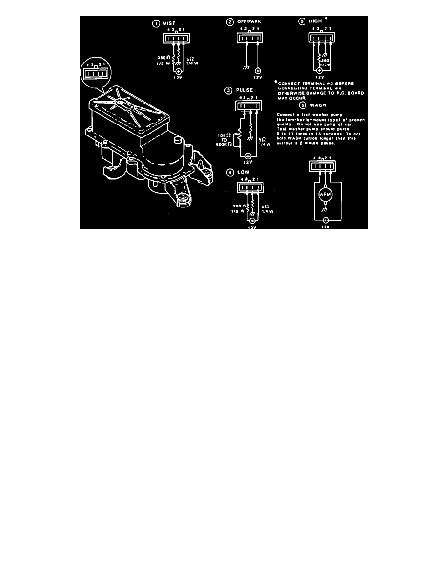
Fig. 10 Permanent Magnet Non-depressed Park Type Windshield Wiper Motor. (Note: The Harness Connector May Be Labeled D-C-B-A Instead Of 1-2-3-4)
Standard (Non-Pulse) Wiper Operation
When ignition is on, battery voltage is supplied to low and high speed contacts in the wiper switch and to motor terminal 4, Fig. 10. Placing wiper
switch in low or high position completes the feed circuit to motor terminal 2 (low speed brush) or terminal 1 (high speed brush), Fig. 10. Current flows
through the armature to ground through the common brush, and the motor runs at the selected speed.
Placing wiper switch in off position connects the motor low speed brush to park switch terminal 3, Fig. 10. Current flows through the closed park
switch contacts, allowing the motor to run at low speed. When wipers reach their lowest point of travel, a cam on the motor output shaft opens the park
switch through an actuating lever, and the motor stops.
Pulse Wiper Operation
In addition to standard wiper system components, models with pulse wipers use a pulse control module and a wiper switch with a variable resistor and
additional contacts to control pulse module operation. Current flow between the wiper motor and switch, and battery voltage to the switch pass through
the pulse control module. However, when the wiper switch is in off, low or high position, the module does not affect system operation.
When the wiper switch is in delay position, voltage is supplied to the pulse module timer through the variable resistor. When the timer circuit becomes
fully charged, the timer switch closes, and voltage is supplied to the motor through a second delay terminal in the wiper switch. As the motor begins to
operate, the park switch closes, the timer switch opens, and voltage is supplied to the motor through a third delay contact which is linked to the park
switch in the wiper switch. When wipers complete their cycle, the park switch opens, the motor stops, and the timer begins to recharge.
This cycle repeats as long as wiper switch is in delay position. Delay period is controlled by varying resistance in the pulse module timer feed circuit.