
Seville STS V8-4.6L VIN 9 (1998)
Most intermittents are caused by faulty electrical connections or wiring, although occasionally a sticking relay or solenoid can be a problem. Some items
to check are:
^
Poor mating of connector halves, or terminals not fully seated in the connector body (backed out).
^
Dirt or corrosion on the terminals. The terminals must be clean and free of any foreign material which could impede proper terminal contact.
^
Damaged connector body, exposing the terminals to moisture and dirt, as well as not maintaining proper terminal orientation with the component
or mating connector.
^
Improperly formed or damaged terminals. All connector terminals in problem circuits should be checked carefully to ensure good contact tension.
Use a corresponding mating terminal to check for proper tension. Refer to Checking Terminal Contact for the specific procedure.
^
The J 35616-A must be used whenever a diagnostic procedure requests checking or probing a terminal. Using the adapter will ensure that no
damage to the terminal will occur, as well as giving an idea of whether contact tension is sufficient. If contact tension seems incorrect, refer to
Checking Terminal Contact for specifics.
^
Poor terminal to wire connection. Some conditions which fall under this description are poor crimps, poor solder joints, crimping over wire
insulation rather than the wire itself, corrosion in the wire to terminal contact area, etc.
^
Wire insulation which is rubbed through, causing an intermittent short as the bare area touches other wiring or parts of the vehicle.
^
Wiring broken inside the insulation. This condition could cause a continuity check to show a good circuit, but if only one or two strands of a
multi-strand type wire are intact, resistance could be far too high.
To avoid any of the above problems when making wiring or terminal repairs, always follow the instructions for wiring and terminal repair detailed in
Wiring Repairs and Connector Repairs. See: General Electrical Diagnosis Procedures/Troubleshooting Tests/Checking Terminal Contact
Symptom Diagnostic Example
The following is an example of a symptom and the correct course of action taken by the technician.
IMPORTANT: Research for possible bulletins, DTCs and the vehicle's service history. A1so, thoroughly screen the customer regarding the problem in
order to complete the repair of the vehicle and completely satisfy the customer when a DTC or a symptom diagnosis is not available.
Verify the Customer Concern, Check the Problem
Customer complaint is the headlamps are inoperative. Verify the normal operating procedure of the circuit and the components that share that
circuit. Refer to Strategy Based Diagnosis.
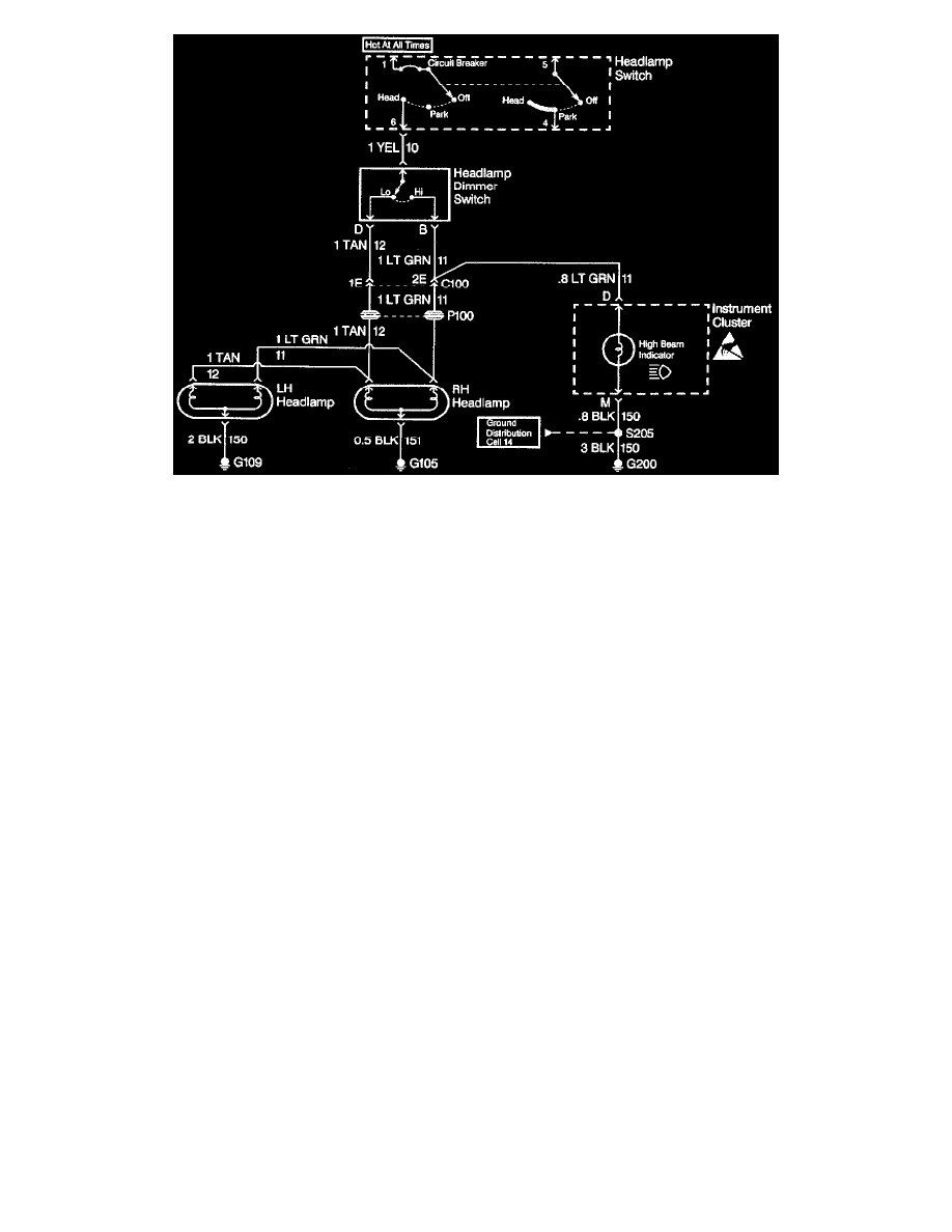
Review the Headlamps Electrical Schematic (Preliminary Checks)
Review the schematic, it is essential to understand how a circuit should work before trying to figure out why it doesn't. After understanding how a
circuit should operate, read the schematic again. this time keeping in mind what has been learned by operating the circuit. Since both the low beam
headlamps are inoperative, ensure that the following components are operating properly.
^
The headlamp Switch.
^
The YEL wire.
^
Low contacts of the Headlamp Dimmer Switch.
^
C100 terminal 1E.
^
The TAN wires.
^
Grounds G105 and G109.
Refer to Strategy Based Diagnosis.