
Seville STS V8-4.6L VIN 9 (1998)
Because frontprobing can be a source of damage to connector terminals. Use extra care in order to avoid deforming the terminal, either by forcing
the test probe too far into the cavity or by using too large of a test probe.
BACKPROBE
IMPORTANT
^
Do not backprobe a sealed connector.
^
After backprobing any connector, check for terminal damage. If terminal damage is suspected, check for proper terminal contact.
Testing For Continuity
Testing For Continuity
WITH A DMM
Continuity tests work well for detecting intermittent shorts to ground and can be performed by setting the DMM to ohms, then pressing the PEAK
MIN MAX button. An audible tone is heard whenever the DMM detects continuity for at least 1 millisecond.
This test checks for continuity along a wire, through a connection or switch.
Note: Refer to DMM Test Probe Notice in Cautions and Notices.
1. Remove the negative battery cable.
2. Place the leads of the DMM in COM (black) and V/ohms (red) inputs.
3. Set the rotary dial of the DMM to ohms.
4. Press the PEAK MIN MAX button.
5. Connect one lead of the DMM to one end of the circuit to test.
6. Connect the other lead to the other end of the circuit.
7. If the DMM displays low or no resistance and a tone is heard the circuit being tested has good continuity.
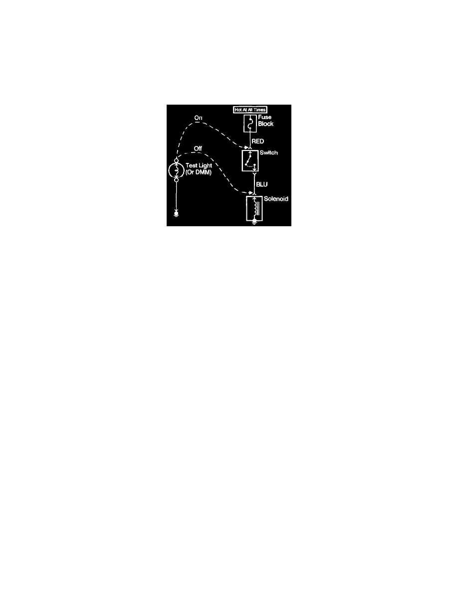
WITH A TEST LIGHT
This test checks for continuity along a wire, through a connection or switch.
Note: Refer to DMM Test Probe Notice in Cautions and Notices.
1. Remove the fuse from the suspect circuit.
2. Connect one lead of the test light to one end of the circuit to test.
3. Connect one end of the circuit to be tested to ground.
4. If the test light is not self-powered connect the other lead to a battery positive voltage source.
5. If the test light illuminates (full intensity) then the circuit being tested has good continuity.
Testing For Electrical Intermittents
Use the following procedure to detect an intermittent circuit that is currently operating normally.
IMPORTANT: The J 39200 must be used to perform the following procedure since the DMM can monitor current, resistance or voltage while
recording the minimum (MIN), and maximum (MAX) values measured.
1. Connect the J 39200 to both sides of a suspected connector, (still connected) or from one end of a suspected circuit to the other.
IMPORTANT: Refer to Troubleshooting with a Digital Multimeter.
2. Select the appropriate voltage mode on the DMM.