
Seville STS V8-4.6L VIN 9 (1998)
3. Press the Range button to select the desired voltage range.
4. Press the MIN MAX button. The DMM displays 100 ms RECORD and emits an audible tone (beep).
IMPORTANT: The DMM is now ready to record and generates an audible tone for any change in voltage. The 100 ms RECORD mode is the amount
of time used to record each snapshot of information used for calculating the AVG voltage.
5. Simulate the condition that is potentially causing an intermittent connection, either by wiggling the connections or the wiring, also by test driving
or performing other operations. If an open or a high resistance condition is created voltage is present and the DMM emits a tone for as long as the
condition exists.
6. Press the MIN MAX button once to display the MAX value and note the value.
7. Press the MIN MAX button twice for the MIN value and note the value.
8. Determine the difference between the MIN and MAX values.
^
If the variation between the recorded MIN and MAX voltage values is one volt or greater an intermittent open or high resistance condition
exists. Repair condition as necessary.
^
If the variation between the recorded MIN and MAX voltage values is less than one volt an intermittent open or high resistance condition does
not exist.
Testing For Poor Connections
Most intermittents are caused by faulty electrical connections or wiring. Occasionally a sticking relay or solenoid can also cause an intermittent failure.
Some items to check are:
^
Poor mating of connector halves or terminals not fully seated in the connector body (backed out).
^
Dirt or corrosion on the terminals.
^
The terminals must be clean and free of any foreign material which could impede proper terminal contact.
^
Damaged connector body causing improper terminal orientation with the component or mating connector.
^
Improperly formed or damaged terminals.
^
Check all connector terminals in problem circuits in order to ensure good contact tension. Use a corresponding mating terminal to check for proper
tension. Refer to Connector Repairs for the specific procedure.
^
Poor terminal to wire connection. Some conditions which fall under this description are poor crimps, poor solder joints, crimping over wire
insulation rather than the wire itself and corrosion in the wire to terminal contact area, etc.
^
Wire insulation which is rubbed through. This causes an intermittent short as the bare area touches other wiring or parts of the vehicle.
^
Wiring broken inside the insulation. This condition could cause a continuity check to show a good circuit but if only one or two strands of a
multi-strand type wire are intact, resistance could be far too high.
In order to avoid any of the above problems when making wiring or terminal repairs always follow the instructions for wiring and terminal repair detailed
in Wiring Repairs and Connector Repairs.
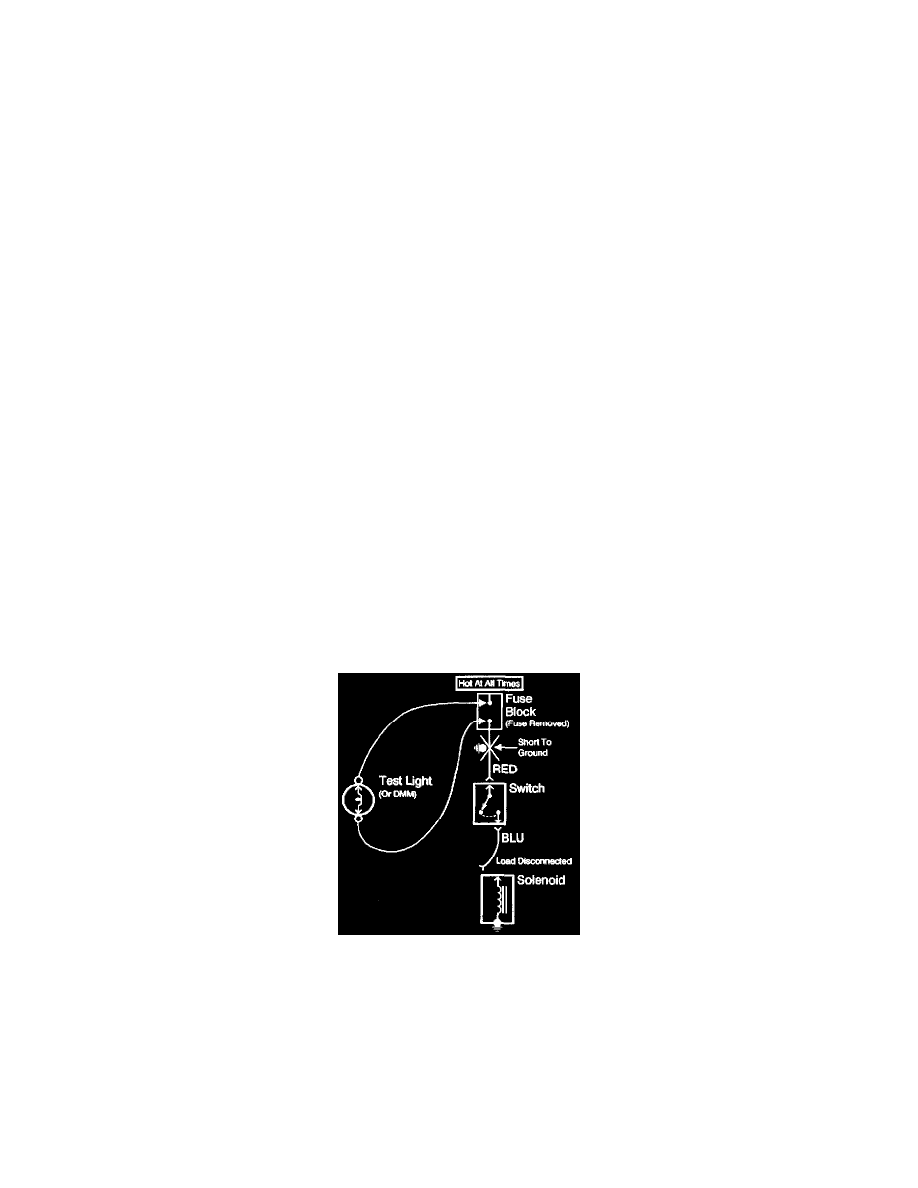
Testing For Short to Ground
This test checks a short to ground along a wire or through a connection, or switch.
Testing For Short To Ground
With A DMM Set To Ohmmeter Function
1. Remove the open fuse.
2. Disconnect the battery.
3. Disconnect the load.
4. Connect one lead of the DMM to the fuse terminal on the load side.
5. Connect the other lead to a known good ground.
6. Beginning near the fuse block, wiggle the harness from side to side. Continue this at convenient points (about 6 inches apart) while watching
the DMM.
7. When the DMM displays low or no resistance, there is a short to ground in the wiring near that point.