
SRX 2WD V8-4.6L VIN A (2004)
-
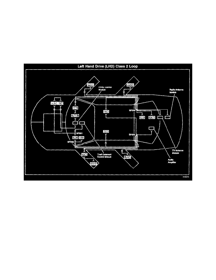
The right rear door module (RRDM)
-
The radio antenna module
-
The TV antenna module
-
The vehicle communication interface module (VCIM)
-
The rear integration module (RIM)
-
The front passenger door module (FPDM)
-
SP300
-
The audio amplifier
-
The left rear door module (LRDM)
-
The driver door switch assembly (DDSA)
-
The driver door module (DDM)
-
The memory seat module (MSM) w/A45
-
SP200 - The theft deterrent control module
Refer to Data Link Connector (DLC) Schematics and the illustration in order to familiarize yourself with the architecture of the class 2 serial data
circuit:
CLASS 2 SERIAL DATA CIRCUIT RIGHT HAND DRIVE (RHD)
The class 2 serial data circuit on this vehicle consists of a hybrid ring and star configuration. Each module on the ring has 2 class 2 serial data circuits
connected to it. If there is 1 open on the ring serial data communication will still take place. If there is more than 1 open on the ring, the modules not
connected to the class 2 serial data circuit will not communicate. If there is 1 open on the star, the module not connected to the class 2 serial data
circuit will not communicate. The following modules and splice packs are connected to the class 2 serial data circuit in a ring fashion:
-
SP201
-
SP303
-
The inflatable restraint sensing and diagnostic module (SDM)
-
SP300
-
The dash integration module (DIM)
-
The radio
-
The HVAC control module
-
The electronic control module (ECM)
-
The electronic brake control module (EBCM)
-
SP200
-
The instrument panel cluster (IPC)
The star has the following 4 splice packs: