
SRX 2WD V8-4.6L VIN A (2004)
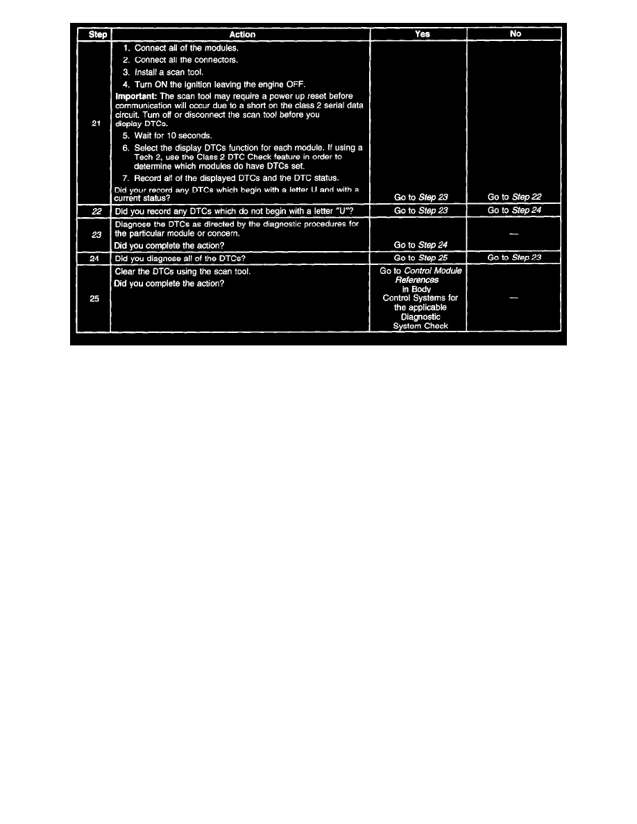
Steps 21-25
The numbers below refer to the step numbers on the diagnostic table.
2. A partial loss of communication in the class 2 serial data circuit uses a different procedure than a total loss of communication of the class 2 serial
data circuit.
4. The following DTCs may be retrieved with a history status. These DTCs are not the cause of the present condition.
-
U1300
-
U1301
-
U1305
6. A State of Health DTC with a history status may be present along with a U1000 or U1255 with a current status. This indicates that the malfunction
occurred when the ignition was on.
10. Normal class 2 serial data communication cannot take place until the power mode master (PMM) module sends the appropriate power mode
message. If the PMM does not send a wake-up message, other modules on the class 2 serial data circuit may not communicate.
12. Disconnecting the splice packs one at a time and attempting to communicate with any module still connected to the class 2 serial data circuit, will
determine whether or not the concern is in the star portion of the class 2 serial data circuit.
13. Connecting the class 2 serial data circuits to the suspect splice pack one at a time while attempting to communicate with any module still
connected to the class 2 serial data circuit, will determine which circuit or module on the star is causing the concern.
14. Splitting the class 2 serial data circuit will help isolate the location of the malfunction. If communication can be established, the concern is located
in the wiring or one of the modules that is no longer connected to the DLC. If communication cannot be established, the concern is located in the
wiring or one of the modules that is still connected to the DLC.
22. If there are no current DTCs that begin with the letter "U", the communication concern has been repaired.
23. The communication concern may have prevented diagnosis of the customer complaint.
Scan Tool Does Not Communicate With High Speed GMLAN Device
SCAN TOOL DOES NOT COMMUNICATE WITH HIGH SPEED GMLAN DEVICE
CIRCUIT DESCRIPTION
Modules connected to the high speed GMLAN serial data circuits monitor for serial data communications on the high speed GMLAN network during
normal vehicle operation. Operating information and commands are exchanged among the modules. When a module detects a bus-off condition a
DTC UO0O1 or U2100 will be set. These DTCs can be retrieved as history only.
DIAGNOSTIC AIDS
The engine will not start when there is a total malfunction of the high speed GMLAN serial data circuits while the engine is not running. The following
conditions may cause a total loss of high speed GMLAN data communication:
-
A short between high speed GMLAN (+) and high speed GMLAN (-) circuits
-
Any of the high speed GMLAN serial data circuits shorted to ground or voltage
-
A module internal malfunction that causes a short to voltage or ground on the high speed GMLAN circuits