
SRX AWD V8-4.6L VIN A (2004)
Body Control Module: Description and Operation
Dash Integration Module (DIM)
DASH INTEGRATION MODULE (DIM)
The various DIM input and output circuits are described in the corresponding functional areas as indicated on the DIM electrical schematics.
The DIM functions include the following:
-
cigar lighter relay control
-
class 2 communication requiring DIM interaction
-
exterior lighting control
-
headlamp washer control
-
hood ajar switch input w/export
-
horn relay control
-
interior lighting control
-
load management
-
low side temperature for HVAC compressor
-
park key lock output
-
power moding control over Class 2 serial data circuit
-
reverse lockout solenoid control
-
steering wheel controls input
-
storage of the clock settings and, sending a message out on the class 2 serial data circuit in response to requests from other modules
-
storage of vehicle options and configuration
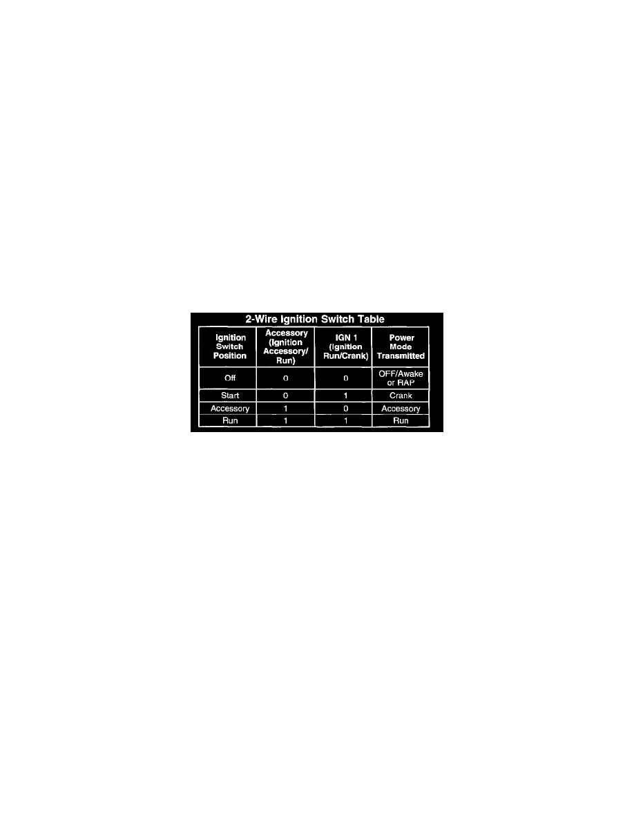
Serial Data Power Mode
On vehicles that have several control modules connected by serial data circuits, one module is the power mode master (PMM). On this vehicle the
PMM is the DIM. The PMM receives 2 signals from the ignition switch.
To determine the correct power mode the PMM uses the following circuits:
-
Accessory voltage
-
Run/Crank voltage
Fail-safe Operation
Since the operation of the vehicle systems depends on the power mode, there is a tail-sate plan in place should the PMM fail to send a power mode
message. The fail-sate plan covers those modules using exclusively serial data control of power mode as well as those modules with discrete ignition
signal inputs.
Serial Data Messages
The modules that depend exclusively on serial data messages for power modes stay in the state dictated by the last valid PMM message until they can
check for the engine run flag status on the serial data circuits. If the PMM tails, the modules monitor the serial data circuit for the engine run flag serial
data. It the engine run flag serial data is True, indicating that the engine is running, the modules tail-sate to RUN. In this state the modules and their
subsystems can support all operator requirements. It the engine run flag serial data is False, indicating that the engine is not running, the modules
tail-safe to OFF-AWAKE. In this state the modules are constantly checking for a change status message on the serial data circuits and can respond to
both local inputs and serial data inputs from other modules on the vehicle.
Discrete Ignition Signals
Those modules that have discrete ignition signal inputs also remain in the state dictated by the last valid PMM message received on the serial data
circuits. They then check the state of their discrete ignition input to determine the current valid state. If the discrete ignition input is active, battery
positive voltage, the modules will tail-sate to the RUN power mode. It the discrete ignition input is not active, open or 0 voltage, the modules will
fail-sate to OFF-AWAKE. In this state the modules are constantly checking for a change status message on the serial data circuits and can respond to
both local inputs and serial data inputs from other modules on the vehicle
Electrical Load Management
The power management function is designed to monitor the vehicle electrical load and determine when the battery is potentially in a high discharge
condition. This is accomplished by using a high accuracy battery voltage reading as an indicator of battery discharge rate. The following six levels of