
SRX RWD V8-4.6L VIN A (2006)
-
Pull to Seat terminals
Some terminals do not require all of the steps shown. Skip the steps that do not apply for your terminal repair. The J-38125 contains further information.
1. Cut off the terminal between the core and the insulation crimp. Minimize any wire loss.For cable seal terminals, remove the seal.
2. Apply the correct cable seal per gage size of the wire, if used.Slide the seal back along the wire in order to enable insulation removal.
3. Remove the insulation.
4. For sealed terminals only, align the seal with the end of the cable insulation.
5. Position the strip in the terminal.For sealed terminals, position the strip and seal in the terminal.
6. Hand crimp the core wings.
7. Hand crimp the insulation wings.For sealed terminals, hand crimp the insulation wings around the seal and the cable.
8. Solder all of the hand crimp terminals excepting Micro-Pack 100.64 size. Soldering Micro-Pack 100 World terminals may damage the terminal.
Terminal Position Assurance Locks
TERMINAL POSITION ASSURANCE LOCKS
The terminal position assurance (TPA) insert resembles the plastic combs used in the control module connectors. The TPA keeps the terminal securely
seated in the connector body. Do not remove the TPA from the connector body unless you remove a terminal for replacement.
Tyco/Amp Connectors (CM 42-Way)
TYCO/AMP CONNECTORS (CM 42-WAY)
TOOLS REQUIRED
J-38125 Terminal Repair Kit
REMOVAL PROCEDURE
1. Locate the connector position assurance (CPA) on the connector body and pull the CPA out. The CPA is on the wire harness side of connector.
2. Disconnect the connector from the component.
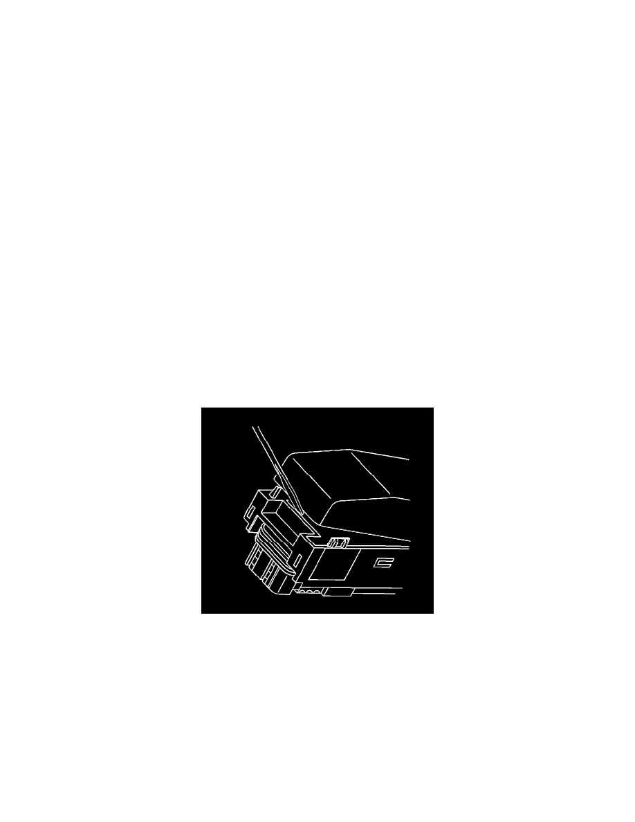
3. Use a small flat-bladed tool to gently pry off the dress cover by inserting the tool under the cover opposite the harness side and prying up.
4. Remove the cover.