
SRX RWD V8-4.6L VIN A (2006)
-
When using the J-35616 GM-Approved Terminal Test Kit, ensure the terminal test adapter choice is the correct size for the connector terminal. Do
not visually choose the terminal test adapter because some connector terminal cavities may appear larger than the actual terminal in the cavity.
Using a larger terminal test adapter will damage the terminal. Refer to the J-35616 GM-Approved Terminal Test Kit label on the inside of the
J-35616 GM-Approved Terminal Test Kit for the correct adapter along with the connector end view for terminal size.
Using Fused Jumper Wires
USING FUSED JUMPER WIRES
TOOLS REQUIRED
J 36169-A Fused Jumper Wire
IMPORTANT: A fused jumper may not protect solid state components from being damaged.
The J 36169-A includes small clamp connectors that provide adaptation to most connectors without damage. This fused jumper wire is supplied with a
20-A fuse which may not be suitable for some circuits. Do not use a fuse with a higher rating than the fuse that protects the circuit being tested.
Connector Position Assurance Locks
CONNECTOR POSITION ASSURANCE LOCKS
The connector position assurance (CPA) is a small plastic insert that fits through the locking tabs of the connector. CPAs are used in various connectors
throughout the vehicle. CPAs are also used in all SIR system electrical connectors. The CPA ensures that the connector halves cannot vibrate apart. You
must have the CPA in place in order to ensure good contact between the mating terminals, of the connector.
Micro .64 Connectors
MICRO.64 CONNECTORS
TOOLS REQUIRED
J-38125 Terminal Repair Kit
REMOVAL PROCEDURE
Follow the steps below in order to remove terminals from Micro 64 connectors.
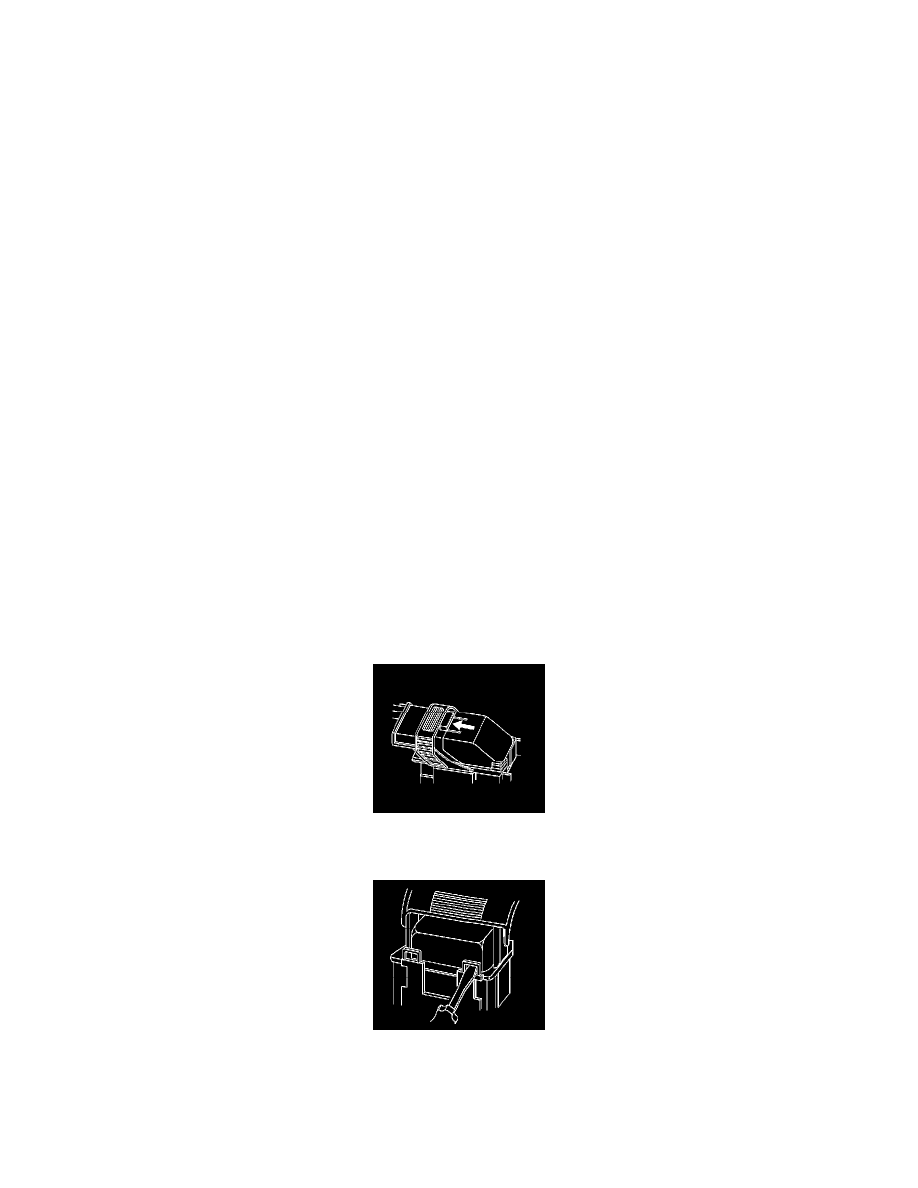
1. Locate the lever lock on the wire dress cover. While depressing the lock, pull the lever over and past the lock.
2. Disconnect the connector from the component.
3. Locate the dress cover locking tabs at the front of the connector. Using a small flat-blade tool push down on one of the locking tabs and pull the
cover up until the dress cover releases. Repeat this procedure for the other locking tab.
4. Once the front 2 locks are unlocked, lift the front of the dress cover and pull it forward.