
STS AWD V6-3.6L (2007)
*
Brake rotor thickness variation MUST be checked BEFORE checking for assembled lateral runout (LRO). Thickness variation exceeding
the maximum acceptable level can cause brake pulsation. Refer to Brake Rotor Thickness Variation Measurement. See: Brake Rotor
Thickness Variation Measurement
1. Matchmark the position of the brake rotor to the wheel studs if this has not been done already.
Important: Whenever the brake rotor has been separated from the hub/axle flange, any rust or contaminants should be cleaned from the
hub/axle flange and the brake rotor mating surfaces. Failure to do this may result in excessive assembled lateral runout (LRO) of the
brake rotor, which could lead to brake pulsation.
2. Inspect the mating surface of the hub/axle flange and the brake rotor to ensure that there are no foreign particles, corrosion, rust, or debris
remaining. If the wheel hub/axle flange and/or if the brake rotor mating surfaces exhibit these conditions, perform the following steps:
1. Remove the brake rotor from the vehicle.
2. Using the J 42450-A, thoroughly clean any rust or corrosion from the mating surface of the hub/axle flange.
3. Using the J 41013, thoroughly clean any rust or corrosion from the mating surface of the brake rotor.
4. Clean the friction surfaces of the brake rotor with denatured alcohol, or an equivalent approved brake cleaner.
3. Install the rotor to the hub/axle flange using the matchmark made prior to removal.
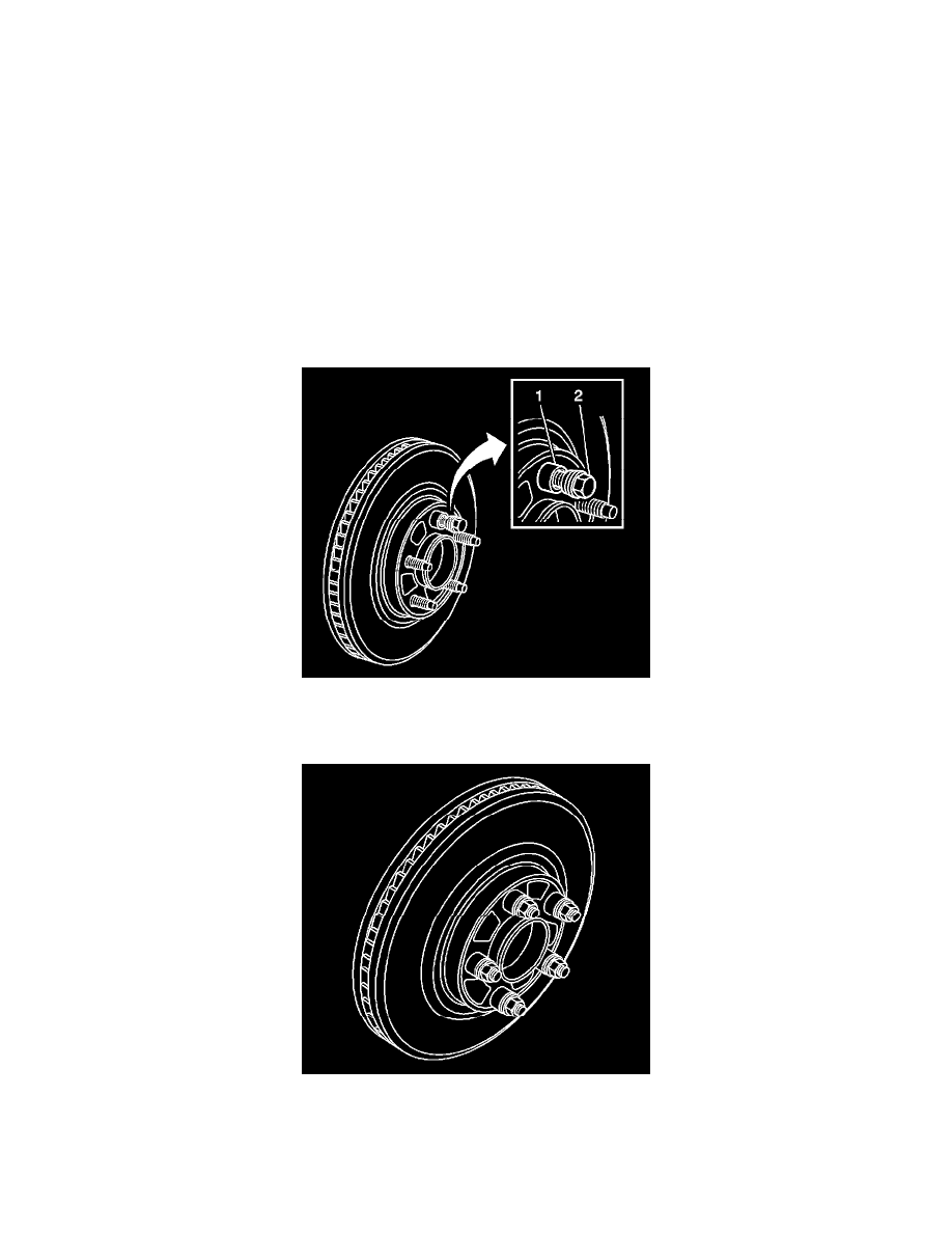
4. Hold the rotor firmly in place against the hub/axle flange and install one of the J 45101-100 (1), and one lug nut (2) onto the upper-most wheel
stud.
5. Continue to hold the rotor secure and tighten the lug nut firmly by hand.
6. Install the remaining J 45101-100 and lug nuts onto the wheel studs and tighten the nuts firmly by hand in a star-pattern.
7. Using the J 39544-KIT, or equivalent, tighten the lug nuts in a star-pattern to specification, in order to properly secure the rotor.
8. If the brake rotor has been REFINISHED or REPLACED with a new rotor, proceed to step 14.
9. If the brake rotor meets the following criteria, proceed to step 10.
*
The rotor is within specifications and is being REUSED