
STS AWD V6-3.6L (2007)
27. Rotate the body of the J 45405 until it bottoms against the die cage.
28. While guiding the finishing cone into the exposed end of pipe to be flared, operate the lever of the J 45405 until the finishing cone bottoms against
the dies.
29. Rotate the hydraulic fluid control valve counterclockwise to the open position to allow the hydraulic forming ram to retract.
30. Loosen the die clamping screw and remove the dies and pipe.
31. If necessary, lightly tap the dies until the die halves separate.
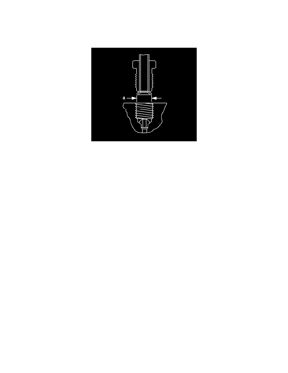
32. Inspect the brake pipe flare for correct shape and diameter (a).
*
6.74-7.10 mm (0.265-0.279 in) flare diameter for 4.76 mm (3/16 in) diameter pipe
*
8.57-9.27 mm (0.344-0.358 in) flare diameter for 6.35 mm (1/4 in) diameter pipe
33. If necessary, using the removed section of brake pipe as a template, shape the new pipe with a suitable brake pipe bending tool.
Important: When installing the pipe, maintain a clearance of 19 mm (3/4 in) from all moving or vibrating components.
34. Install the pipe to the vehicle with the appropriate brake pipe unions, as required.
35. If previously released, secure the brake pipe to the retainers.
36. Bleed the hydraulic brake system.
37. With the aid of an assistant, inspect the brake pipe flares for leaks by starting the engine and applying the brakes.
Front Brake Hose Replacement
Front Brake Hose Replacement
Caution: Refer to Brake Fluid Irritant Caution.
Notice: Refer to Brake Fluid Effects on Paint and Electrical Components Notice.
Removal Procedure
1. Raise and suitably support the vehicle. Refer to Vehicle Lifting.
2. Remove the tire and wheel assembly.
3. Clean all dirt and foreign material from the brake hose and the brake pipe fittings.
4. Remove the wheel speed sensor wiring harness retainers from the brake hose bracket.