
STS AWD V6-3.6L (2007)
Hydraulic Control Assembly - Antilock Brakes: Service and Repair
Brake Pressure Modulator Valve Replacement
Removal Procedure
Caution: Refer to Brake Fluid Irritant Caution.
Caution: For safety reasons, the brake pressure modulator valve assembly must not be repaired, the complete unit must be replaced. With the
exception of the EBCM, no screws on the brake pressure modulator valve assembly may be loosened. If screws are loosened, it will not be
possible to get the brake circuits leak-tight and personal injury may result.
Notice: Refer to Brake Fluid Effects on Paint and Electrical Components Notice.
Important:
*
The ignition switch must be placed in the OFF mode ONLY, before disconnecting the negative battery cable during this
procedure. If the ignition switch is accidentally placed into ignition ON engine OFF mode, the control modules will be activated
and disconnecting the negative cable will cause various DTC's to be set. Refer to Keyless Entry System Description and Operation.
*
After the ignition switch is placed into OFF mode, a waiting period of 2 minutes must be observed to allow the high-speed LAN
control modules to deactivate before disconnecting or connecting the negative battery cable during this procedure. If the waiting
period is not observed, one or more of these control modules may still be activated, this will cause various DTC's to be set.
Place the ignition switch into OFF mode. DO NOT place the ignition switch into ignition ON engine OFF mode.
1. Wait for a minimum of 2 minutes to allow the high-speed LAN control modules to deactivate.
Important: The area around the electronic brake control module (EBCM) must be free from loose dirt to prevent contamination of
disassembled ABS components.
2. Thoroughly clean all contaminants from around the EBCM.
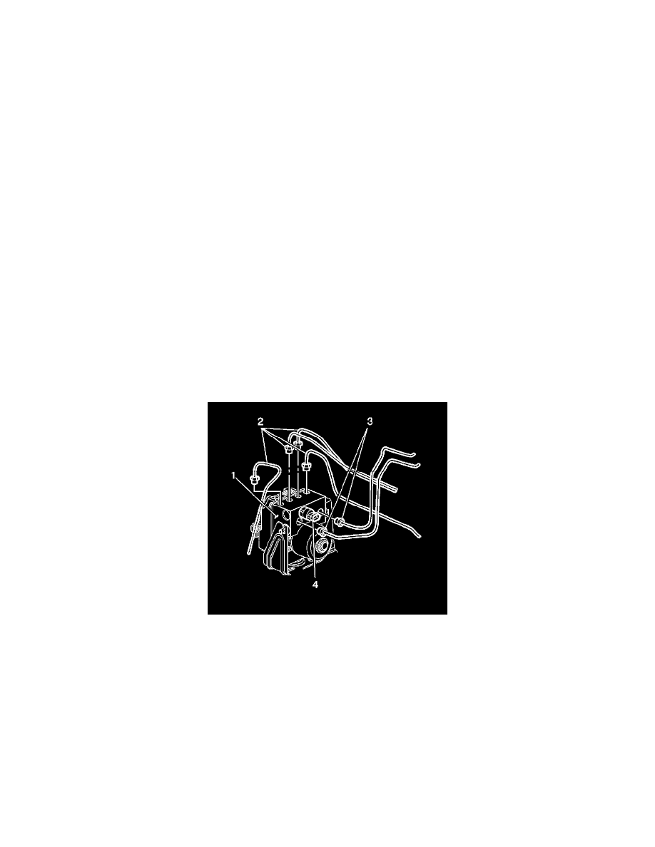
Important: Record the location of all brake pipes to the brake pressure modulator valve (BPMV) for use as an aid during installation.
3. Remove the 2 master cylinder brake pipes (3) from the BPMV (1).
4. Clean any brake fluid spillage from the BPMV (1).
5. Raise and support vehicle. Refer to Vehicle Lifting.
6. Remove the air deflector shield.
Important: It is not necessary to remove the washer solvent container from the vehicle.
7. Remove the washer solvent container.
8. Remove the 4 wheel brake pipes (2) from the BPMV (1).
Notice: To prevent equipment damage, never connect or disconnect the wiring harness connection from the EBCM with the ignition switch in the
ON position.
9. Press the retainer on the EBCM electrical connector (1).