
STS AWD V8-4.6L VIN A (2006)
11. Insert the J 38125-560 (GM P/N 15314260) into the 2 triangular cavities on each side of the terminal at the front of the connector. See the release
tool cross reference in the Reference Guide of the J-38125 to ensure that the correct release tool is used.
12. Carefully pull the terminal out of the connector. Always remember never use force when pulling a terminal out of a connector. If the terminal is
difficult to remove, repeat the entire procedure.
TERMINAL REPAIR PROCEDURE
Use the appropriate terminal and follow the instructions in the J-38125.
TERMINAL REPLACEMENT PROCEDURE
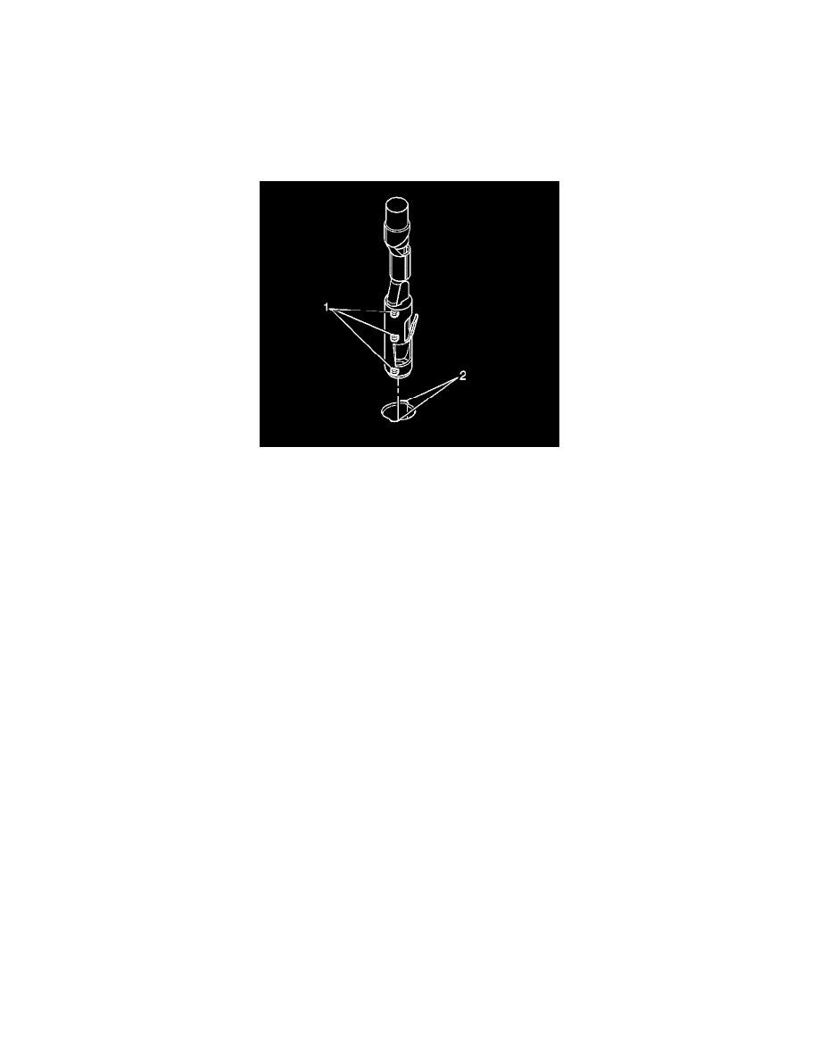
1. Prior to installation the terminal must be aligned so the (1) coding lugs align with the (2) coding grooves on the connector.
2. Once the terminal is aligned, slide the terminal into the cavity until the retainer has engaged in the cavity of the connector.
3. Slide the TPA in the connector body and seat it using a small flat bladed tool. The TPA is seated when it is flush with the contact housing.
4. Secure the wires to the connector body using a tie wrap and replace the dress cover and grommet.
Bosch Connectors (2.8 JPT)
BOSCH CONNECTORS (2.8 JPT)
TOOLS REQUIRED
J-38125 Terminal Repair Kit
TERMINAL REMOVAL PROCEDURE
1. Pull out the slider on the connector position assurance (CPA) until it is at the end of its travel.
2. Disconnect the connector from the component.
3. Remove the wire dress cover, if necessary.
4. Push the wire side of the terminal that is being removed toward the connector and hold it in position.