
STS AWD V8-4.6L VIN A (2006)
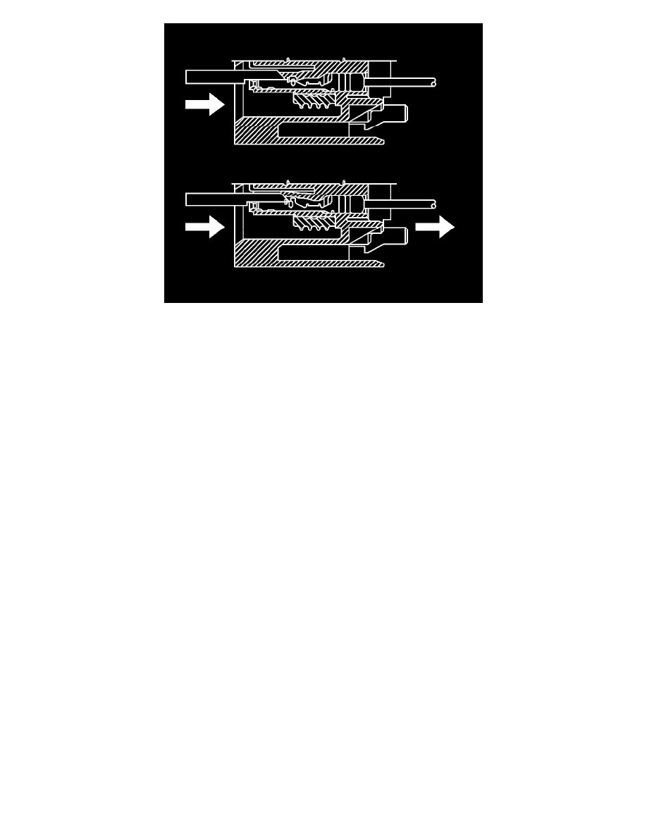
9. The illustration shows a cutaway view of the connector to aid the technician in releasing the terminal retainer.
10. See the release tool cross reference in the Reference Guide of the J-38125 Terminal Repair Kit to ensure that the correct release tool is used.
TERMINAL REPAIR PROCEDURE
Refer to the terminal crimping procedure in the Reference Guide of the J-38125 Terminal Repair Kit.
TERMINAL REPLACEMENT PROCEDURE
After the terminal is crimped to the wire, perform the following procedure in order to replace the terminal.
1. Slide the new terminal into the correct cavity at the back of the connector.
2. Push the terminal into the connector until it locks into place. The new terminal should be even with the other terminals. Insure that the terminal is
locked in place by gently pulling on the wire.
3. To assemble the connector, reverse the connector disassembly procedure.
Terminal Position Assurance Locks
TERMINAL POSITION ASSURANCE LOCKS
The terminal position assurance (TPA) insert resembles the plastic combs used in the control module connectors. The TPA keeps the terminal securely
seated in the connector body. Do not remove the TPA from the connector body unless you remove a terminal for replacement.
Tyco/Amp Connectors (CM 42-Way)
TYCO/AMP CONNECTORS (CM 42-WAY)
TOOLS REQUIRED
J-38125 Terminal Repair Kit
REMOVAL PROCEDURE
1. Locate the connector position assurance (CPA) on the connector body and pull the CPA out. The CPA is on the wire harness side of connector.
2. Disconnect the connector from the component.