
STS RWD V8-4.6L (2007)
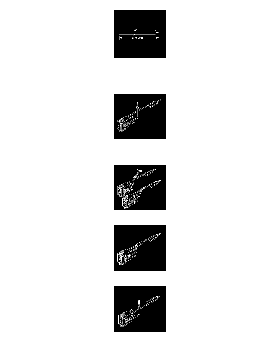
25. Cut two 6.1 m (20 ft) deployment wires from a 0.8 mm (18 gage) or thicker multi-strand wire. Use these wires to fabricate the deployment
harness.
26. Strip 13 mm (0.5 in) of insulation from both ends of the wires cut in the previous step.
27. Twist together one end from each of the wires in order to short the wires. Deployment wires shall remain shorted, and not connected to a power
source until you are ready to deploy the side air bag module and pretensioner.
28. Twist together 2 connector wire leads (the high circuits from side air bag and pretensioner ) to one sets of deployment wires. Refer to SIR
Connector End Views in order to determine the correct circuits. See: Diagrams/Connector Views
29. Inspect that the 3-wire connection is secure.
30. Bend flat the twisted connection.
31. Secure and insulate the 3-wire connection to deployment harness using electrical tape.
32. Twist together 2 connector wire leads (the low circuits from side air bag and pretensioner ) to one sets of deployment wires. Refer to SIR
Connector End Views in order to determine the correct circuits. See: Diagrams/Connector Views