
Astro Van 2WD V6-4.3L VIN X (2002)
Engine Control Module: Description and Operation
General Information
The Powertrain Control Module (PCM) is designed to maintain exhaust emission levels while maintaining excellent driveability and fuel efficiency. The
PCM controls the following operations:
^
The fuel control
^
The Ignition Control (IC)
^
The Knock Sensor (KS) system
^
The automatic transmission shift functions
^
The manual transmission
^
The cruise control enable, if so equipped
^
The generator
^
The Evaporative Emissions (EVAP) purge
^
The A/C clutch control, if so equipped
^
The Secondary Air Injection (AIR), if so equipped
^
The Exhaust Gas Recirculation (EGR)
The PCM controls all ignition system functions, and constantly corrects the basic spark timing. The PCM monitors information from various sensor
inputs that include the following:
^
The Throttle Position (TP) sensor
^
The Engine Coolant Temperature (ECT) Sensor
^
The Mass Airflow (MAF) Sensor
^
The Intake Air Temperature (IAT) Sensor
^
The Vehicle Speed Sensor (VSS)
^
The transmission gear position or range information sensors
^
The engine Knock Sensors (KS)
Basic Knowledge Required
Without a basic knowledge of electricity, it will be difficult to use the diagnostic procedures contained. You should understand the basic theory of
electricity and know the meaning of voltage (volts), current (amps) and resistance (ohms). You should understand what happens in a circuit with an open
or a shorted wire. You should be able to read and understand a wiring diagram.
Engine Controls Information
The driveability and emissions information describes the function and operation of the Powertrain Control Module (PCM).
The computers and control systems information contains the following:
^
Component locations
^
Wiring diagrams
^
PCM terminal end view and terminal definitions
^
Powertrain On-Board Diagnostic (OBD) System Check
^
Diagnostic Trouble Code (DTC) tables
The Component System includes the following items:
^
Component and circuit description
^
On-vehicle service for each sub-system
^
Functional checks and diagnostic tables
The DTCs also contain diagnostic support information containing circuit diagrams, circuit or system information, and helpful diagnostic information.
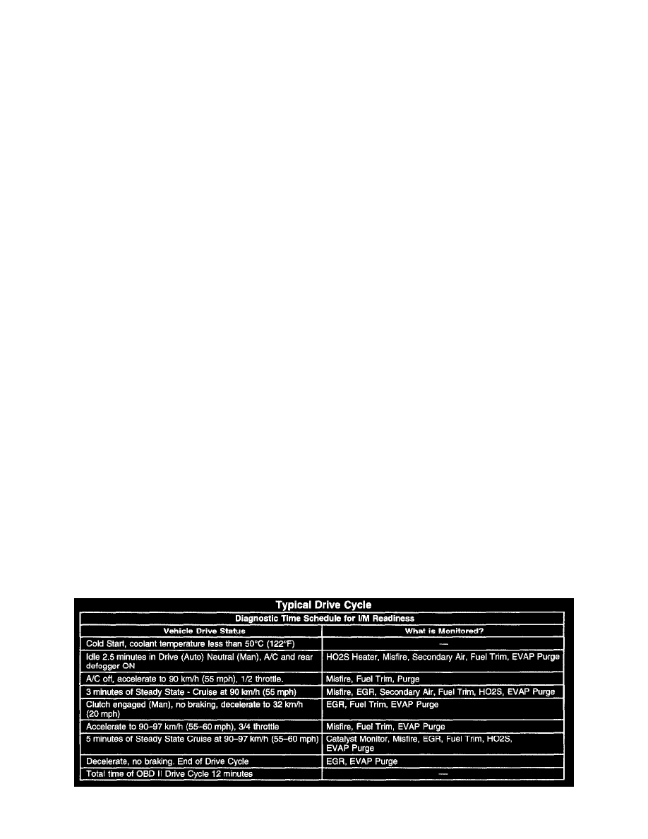
Typical Drive Cycle